
Showing posts with label Hobby Circuits. Show all posts

Monday, June 27, 2011

Object Counter Circuit


Presented here is the cheapest 8-digit programmable object or event counter. It is a fail-proof, fool-proof, power failure-proof, one evening project. A general-purpose (arithmetic) calculator has some inherent shortcomings which can, however, be used in many ways by proper programming sequences.
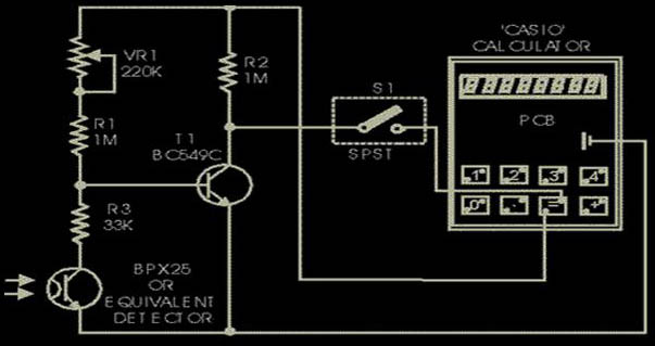
click to enlarge

For example, there is no squaring key in a general-purpose calculator, but it can not only square it has even the inherent capability of a single touch successive multiplication, thus giving us a choice of making a geometric progression (G.P.) or successive addition or forming an arithmetic progression (A.P.). For example, operating the keys 5,x,=,=,... you obtain the G.P. 5,25,125,625,... or by operating keys 5,x,4,=,=,=,..., you get the G.P.: 4,20, 100,500,... Next, operate keys: 5,+, 2,=,=,... to get the A.P.: 5,7,9,11,13,... The latter facility (A.P.) has been used here to count the objects by programming the calculator keys 1,+,=,=,... When you open the calculator (such as ‘Casio’), you will find that the conductive silicon key pads bridge the two terminals of a key, when depressed. Locate the switch terminals for (=) key and check the polarity of the terminals with respect to the battery negative. The terminal which is found to be positive is to be connected to the junction of R2 and VR1, and the other terminal is to be connected to switch S1 as shown in the figure. The negative battery terminal is to be connected to emitters of photo-transistor and transistor T1. (There may be slight difference in the use of key terminals in different brands of calculators.) The optical sensor used here is BPX25, a very sensitive photo-transistor which has a built-in lens to focus the incident light on to the chip. Only two leads, emitter and collector, have been used. When light falls on the sensor, it conducts as if it had got forward biased. A variable resistor of 220k in series with another fixed resistor of 1 M (selected by trial) has been used at the base of transistor T1 (BC149C/BC 549C) to set the threshold level for its conduction, depending upon the intensity of light used. When light is obstructed, BPX goes to cut-off, transistor T1 conducts and the terminal of (=) key which is connected via switch S1 (assuming closed), goes low. This is equivalent to depression of the (=) key. When light again falls on the sensor, it conducts and the base of transistor T1 goes low, throwing it to cut-off, so that its collector and hence the (=) key gets connected to the positive bus via 1 M resistor R2. A pulse is passed on and the calculator advances by 1. Current drain from the battery is less than 50 µA, which a button cell can easily provide. The counter is slow but there is no switch debouncing effect present, which makes the counter highly reliable and ideal as a slow event counter in applications such as visitor counter. Further, the circuit is auto-locked, since any resetting is possible only when BPX is in the cut-off position, i.e., in darkness. To program, cover the phototran- sistor and operate keys : 1,+,=. In case of a deadlock in programming, miniature switch S1 may be used to enable isolation of the (=) key. Set the 220k preset according to the ambient and the incident light, so that the calculator counts when light is cut-off and again allowed to fall when obstruction is removed. If it is used to count visitors in a well day-lighted environment, only a white washed wall or a white paper pasted on the opposite door panel is sufficient. For indoor applications, a specific source of light is required. Both the source of light as well as the BPX should then be mounted in opaque (preferably black) tubes and a lens be fitted in the light-source tube to focus the light on to the photo-transistor. BC149C/549C is preferred due to its large current gain of the order of 300 at 10 µA, compared to 150 that of BC548B, so that the instrument becomes more sensitive.

Water Tank Overflow Preventer


There is practically no house without an overhead tank (OHT). People who use electrically-operated water pumps for filling the OHT find it very inconvenient to switch off the pump when their overhead tank starts overflowing, specially when they are busy. So there is plenty of water wastage as well as wastage of power (consumed by the pump). However, there is a solution to get rid of this headache. 
click to enlarge

The circuit given here will switch off the pump and also generate a melodious tune when the overhead tank gets filled up to the maximum desired level. All you have to do is switch off the power supply to the circuit when you are relatively free. The heart of the circuit is the CMOS latch CD4001. Usually the latch can be operated in two modes, namely, set and reset mode, i.e. the latch output can be set to logic 1 or reset to logic 0 by applying appropriate active low level input signal to pins 1 and 13, respectively. Here, in the given circuit, the set point is pin 1 and the reset point is pin 13. The inverted output of the latches are obtained at pins 3 and 11, respectively. When the circuit is powered there is a voltage drop at pin 1 due to the resistor-capacitor R1-C1 combination. The values of resistor R1 and C1 are chosen in such a way that pin 1 is low for about two seconds which is sufficient to energise the relay through transistor T1 and thus the pump starts running. When sufficient water gets filled in the overhead tank, switch S1 in the sensing unit, in the overhead tank as shown in Fig. 2, sends an active low signal to pin 13 which resets latch gate N1 output to logic 0. This causes transistor T1 to stop conducting, thereby de-energising the relay and shutting down the pump. At the same time, the output at pin 11 of gate N2 will be logic 1. This results in conduction of transistor T2 and melodious buzzer sounds. The green LED also lights up while the red LED, which remains on as long as the relay remains energised, gets switched off when water reaches the specified level in the overhead tank. The circuit possesses the following advantages:
1.    Special sensing mechanism (easy to build) is used to sense the water level in the overhead tank.
2.    One can replace CD4011 with IC 7400. In that case, a 5.1V zener may be connected additionally between pin 14 of IC1 and the ground.
The circuit can be easily fabricated on a general-purpose PCB.

Night Rider Light For Bikes


Always looking for ways to be seen at night. So wanted something that was a novelty and would catch the motorists eye. So looking around at  fellow cyclists rear lights, Its is a Hobby circuit for bikes,'NITE-RIDER'. NINE extra bright LED's running from left to right and right to left continuously. It could be constructed with red LEDs for use on the rear of the bike or white LED's for an extra eye catcher on the front of the bike.

click to enlarge


All IC's are CMOS devices so that a 9V PP3 battery can be used, and the current drawn is very low so that it will last as long as possible.


The circuit comprises of ...


1 555 timer IC4.
1 4027 flip flop IC1.
2 4017 Decade Counter IC2 and IC3.
3 4071 OR gate IC5, IC6 and IC7.
1 470 Ohm resistor 1/4 watt R3.
2 10K resistors 1/4 watt R1 and R2.
1 6.8UF Capasitor 16V C1.
9 Super brght LED's 1 to 9.
1 9V PP3 Battery.
1 single pole switch SW1.
1 Box.


How The Circuit Works.


IC4, C1, R1 and R2 are used for the clock pulse which is fed to both the counters IC2 and IC3 Pin 14.


IC1 is a Flip Flop and is used as a switch to enable ether IC2 or IC3 at pin 13.


IC7a detects when ether IC2 or IC3 has reached Q9 of the counter pin 11.


IC5, IC6 and IC7a protects the outputs of the counters IC2 and IC3 using OR gates which is then fed to the Anodes of the
LED's 1 to 9

LEDs Display


The circuit presented here uses bicolour LEDs to generate a display in three colours, namely, red,green, and yellowish green. Transistors T1 through T20 form a grid to which common-cathode bicolour LEDs (LED1 through LED10) are connected. 
click to enlarge

 Transistors T1 through T10 have their collector terminals connected to the emitter of transistor T21. Similarly, transistors T11 through T20 have their collector terminals connected to the emitter of transistor T22. The bases of each pair of transistors (i.e.  T1 and T11, T2 and T12,…, T10 and T20) are tied to outputs Q0, Q1,…, Q9, respectively, of IC1 (CD4017) through 10-kiloohm resistors as shown in the figure. Positive supply to collectors of transistors T1 through T10 is controlled by transistor T21. Similarly, positive supply to collectors of  transistors T11 through T20 is controlled by transistor T22.
IC1 and IC2 are decade counters. Clock pulse to IC1 is provided by the oscillator circuit comprising NOR gates N1 and N2. The outputs of IC1 advance sequentially  with each clock. (Any other source of squarewave pulses also serves the purpose.)IC2 is used to select the mode of display. Clock input pin 14 of IC2 is connected to Q9 output of IC1. Thus IC2 receives one pulse after every ten pulses received by IC1.
  When the circuit is switched on, Q0 output of IC2 is active high. Thus transistor T21 gets forward biased via diode D3 and it conducts to extend positive supply to transistors T1 through T10. Transistors T1 through T10 are forward biased sequentially by Q0 through Q9 outputs of IC1, i.e. at a time only one of these ten transistors is forward biased (on). Thus only red LED parts of bicolour LEDs light up sequentially.  Transistor T22 is not conducting at this moment.) When red LED part of LED10 glows, IC2 receives a clock pulse and its Q1 output goes high. Transistor T21 still conducts, as it is forward biased through diode D6, and next again via diode D5. Thus red LEDs complete two more glowing sequences.
 After completion of the third glowing sequence of red LEDs, when Q3 output of IC2 goes high, transistor T21 stops conducting and T22 starts conducting with the next three sequences of green LEDs of bicolour LEDs (LED1 through LED10) glowing sequentially. After completion of three sequences of green LEDs, output Q6 of IC2 goes high.
Now both transistors T21 and T22 conduct due to diodes D1 and D2. Thus both red and green LEDs in bicolour LEDs (LED1 through LED10) glow sequentially. The effect of red and green LEDs glowing together is a distinct yellowish orange colour. This sequence repeats four times.
Thereafter, the whole sequence repeats, starting with red LEDs. Thus the bicolour LED display shows three colours—red, green, and yellowish green—one after the other. The speed of display can be controlled by preset VR1. One can omit automatic selection of different colours by omitting IC2 and replacing connections to pins 3, 5, and 7 of IC2 with SPDT switches. (Thus diodes D3-D12 are also omitted.)

Dual Output Dispaly


This circuit lights up ten bulbs sequentially, first in one direction and then in the opposite direction, thus presenting a nice visual effect. In this circuit, gates N1 and N2 form an oscillator. The output of this oscillator is used as a clock for BCD up/down counter CD4510 (IC2).
click to enlarge

 Depending on the logic state at its pin 10, the counter counts up or down. During count up operation, pin 7 of IC2 outputs an active low pulse on reaching the ninth count. Similarly, during countdown operation, you again get a low-going pulse at pin 7.
 This terminal count output from pin 7, after inversion by gate N3, is connected to clock pin 14 of decade counter IC3 (CD4017) which is configured here as a toggle flip-flop by returning its Q2 output at pin 4 to reset pin 15. Thus output at pin 3 of IC3 goes to logic 1 and logic 0 state alternately at each terminal count of IC2.
 Initially, pin 3 (Q0) of IC3 is high and the counter is in count-up state. On reaching ninth count, pin 3 of IC3 goes low and as a result IC2 starts counting down. When the counter reaches 0 count, Q2 output of IC3 momentarily goes high to reset it, thus taking pin 3 to logic 1 state,
and the cycle repeats.
 The BCD outputs of IC2 are connected to 1-of-10 decoder CD4028 (IC4). During count-up operation of IC2, the outputs of IC4 go logic high sequentially from Q0 to Q9 and thus trigger the triacs and lighting bulbs 1 through 10, one after the other. Thereafter, during count-down operation of IC2, the bulbs light in the reverse order, presenting a wonderful visual effect.

Security Alarm for Audio Player


This small circuit, based on popular CMOS NAND chip CD4093, can be effectively used for protecting your expensive car audio system against theft.
click to enlarge

 When 12V DC from the car battery is applied to the gadget (as indicated by LED1) through switch S1, the circuit goes into standby mode. LED inside optocoupler IC1 is lit as its cathode terminal is grounded via the car audio (amplifier) body. As a result, the output at pin 3 of gate N1 goes low and disables the rest of the circuit.
 Whenever an attempt is made to remove the car audio from its mounting by cutting its connecting wires, the optocoupler immediately turns off, as its LED cathode terminal is hanging. As a result, the oscillator circuit built around gates N2 and N3 is enabled and it controls the ‘on’/‘off’ timings of the relay via transistor T2. (Relay contacts can be used to energise an emergency beeper, indicator, car horns, etc, as desired.) Different values of capacitor C2 give
different ‘on’/‘off’ timings for relay RL1 to be ‘on’/‘off’. With 100μF we get approximately 5 seconds as ‘on’ and 5 seconds as ‘off’ time.
 Gate N4, with its associated components, forms a self-testing circuit. Normally, both of its inputs are in ‘high’ state. However, when one switches off the ignition key, the supply to the car audio is also disconnected. Thus the output of gate N4 jumps to a ‘high’ state and it provides a differentiated short pulse to forward bias transistor T1 for a short duration. (The combination of capacitor C1 and resistor R5 acts as the differentiating circuit.) s a result, buzzer in the collector terminal of T1 beeps for a short duration to announce that the security circuit is intact. This ‘on’ period of buzzer can be varied by changing the values of capacitor C1 and/or resistor R5.
  After construction, fix the LED and buzzer in dashboard as per your requirement and hide switch S1 in a suitable location. Then connect lead A to the body of car stereo (not to the body of vehicle) and lead B to its positive lead terminal. Take power supply for the circuit from the car battery directly.
Caution. This design is meant for car audios with negative ground only.

Sunday, June 19, 2011

LED Magic Lights


The circuit as shown in the figure employs 14 bi-colour (red and green) LEDs having three terminals each. Different dancing colour patterns are produced using this circuit since each LED can produce three different colours. 
click to enlarge

The middle terminal (pin 2) of the LEDs is the common cathode pin which is grounded. When a positive voltage is applied to pin 1, it emits red light. Similarly, when positive voltage is applied to pin 3. It  emits green light. And when positive voltage is simultaneously applied to its pins 1 and 3, it emits amber light. The circuit can be used for decorative lights.
 IC1 (555) is used in astable mode to generate clock signal for IC2 and IC3 (CD4518) which are dual BCD counters. Both counters of each of these ICs have been cascaded to obtain 8 outputs from each. The outputs from IC2 and IC3 are connected to IC4 through IC7 which are BCD to 7-segment latch/decodor/driver ICs. Thus we obtain a total of 14 segment outputs from each of the IC pairs consisting of IC4 plus IC5 and IC6 plus IC7. While outputs from former pair are connected to pin No. 1 of all the 14 bi-colour LEDs via current limiting resistors, the ouputs of the latter pair are similarly connected to pin No.3 of all the bi-colour LEDs to get a magical dancing lights effect.

Twitter Delicious Facebook Digg Stumbleupon Favorites More