Showing posts with label Automobile circuits. Show all posts

Monday, June 27, 2011

Motor Speed controler

 
The circuits shown below are a few of many suggested circuits as published by SCR and TRIAC manufacturers and cannot be construed as beeing the exact application for your requirements and I cannot be held responsible for their use and end results . 

click to enlarge

It is suggested that the subject of TRIAC and SCR as well as motor drive control systems be researched before making a final decision as to the application of these control circuits .
For satisfactory and safe results, knowing the exact type of motor you wish to control is of prime importance and all data available should be obtained before you contemplate to add any drive control circuits . Mount all SCR's and Triac on heatsink . Use current rated stranded wiring as required .
If you cannot find the SCR's and TRIAC's suggested in the circuits you may be able to find a substitute following this link Cross References
Some links to SCR's,TRiac's and motor control application notes:

Thyristors
Application Notes
Triac Data
NTE Triac Selection
NTE SCR Selection
You can use a transformer with up to 12 amps output current with corresponding fuse value . Use No.12-14 stranded wiring to battery connection with heavy duty clips .
Mount Rectifiers and SCR's on heatsink . You can use a mA meter with a shunt resistor . See
Metering a power supply .
Note The rectifiers and SCR's value as quoted can be changed to lesser values as required for lower current output .


Night Rider Light For Bikes


Always looking for ways to be seen at night. So wanted something that was a novelty and would catch the motorists eye. So looking around at  fellow cyclists rear lights, Its is a Hobby circuit for bikes,'NITE-RIDER'. NINE extra bright LED's running from left to right and right to left continuously. It could be constructed with red LEDs for use on the rear of the bike or white LED's for an extra eye catcher on the front of the bike.

click to enlarge


All IC's are CMOS devices so that a 9V PP3 battery can be used, and the current drawn is very low so that it will last as long as possible.


The circuit comprises of ...


1 555 timer IC4.
1 4027 flip flop IC1.
2 4017 Decade Counter IC2 and IC3.
3 4071 OR gate IC5, IC6 and IC7.
1 470 Ohm resistor 1/4 watt R3.
2 10K resistors 1/4 watt R1 and R2.
1 6.8UF Capasitor 16V C1.
9 Super brght LED's 1 to 9.
1 9V PP3 Battery.
1 single pole switch SW1.
1 Box.


How The Circuit Works.


IC4, C1, R1 and R2 are used for the clock pulse which is fed to both the counters IC2 and IC3 Pin 14.


IC1 is a Flip Flop and is used as a switch to enable ether IC2 or IC3 at pin 13.


IC7a detects when ether IC2 or IC3 has reached Q9 of the counter pin 11.


IC5, IC6 and IC7a protects the outputs of the counters IC2 and IC3 using OR gates which is then fed to the Anodes of the
LED's 1 to 9

Security Alarm for Audio Player


This small circuit, based on popular CMOS NAND chip CD4093, can be effectively used for protecting your expensive car audio system against theft.
click to enlarge

 When 12V DC from the car battery is applied to the gadget (as indicated by LED1) through switch S1, the circuit goes into standby mode. LED inside optocoupler IC1 is lit as its cathode terminal is grounded via the car audio (amplifier) body. As a result, the output at pin 3 of gate N1 goes low and disables the rest of the circuit.
 Whenever an attempt is made to remove the car audio from its mounting by cutting its connecting wires, the optocoupler immediately turns off, as its LED cathode terminal is hanging. As a result, the oscillator circuit built around gates N2 and N3 is enabled and it controls the ‘on’/‘off’ timings of the relay via transistor T2. (Relay contacts can be used to energise an emergency beeper, indicator, car horns, etc, as desired.) Different values of capacitor C2 give
different ‘on’/‘off’ timings for relay RL1 to be ‘on’/‘off’. With 100μF we get approximately 5 seconds as ‘on’ and 5 seconds as ‘off’ time.
 Gate N4, with its associated components, forms a self-testing circuit. Normally, both of its inputs are in ‘high’ state. However, when one switches off the ignition key, the supply to the car audio is also disconnected. Thus the output of gate N4 jumps to a ‘high’ state and it provides a differentiated short pulse to forward bias transistor T1 for a short duration. (The combination of capacitor C1 and resistor R5 acts as the differentiating circuit.) s a result, buzzer in the collector terminal of T1 beeps for a short duration to announce that the security circuit is intact. This ‘on’ period of buzzer can be varied by changing the values of capacitor C1 and/or resistor R5.
  After construction, fix the LED and buzzer in dashboard as per your requirement and hide switch S1 in a suitable location. Then connect lead A to the body of car stereo (not to the body of vehicle) and lead B to its positive lead terminal. Take power supply for the circuit from the car battery directly.
Caution. This design is meant for car audios with negative ground only.

Car Anti-Theft Wireless Alarm


This FM radio-controlled anti- theft alarm can be used with any  ehicle having 6- to 12-volt DC supply system. The mini VHF, FM transmitter is fitted in the vehicle at night when it is parked in the car porch or car park. The receiver unit with CXA1019, a single IC-based FM radio module, which is freely available in the market at reasonable rate, is kept inside. Receiver is tuned to the transmitter's frequency. When the transmitter is on and the signals are being received by FM radio receiver, no hissing noise is available at the output of receiver.
click to enlarge

Thus transistor T2 (BC548) does not conduct. This results in the relay driver transistor T3 getting its forward base bias via 10k resistor R5 and the relay gets ener- gised. When an intruder tries to drive the car and takes it a few metres away from the car porch, the radio link betw- een the car (transmitter) and alarm (receiver) is broken. As a result FM radio module gene-rates hissing noise. Hissing AC signals are coupled to relay switching circ- uit via audio transformer. These AC signals are rectified and filtered by diode D1 and capacitor C8, and the resulting positive DC voltage provides a forward bias to transistor T2. Thus transistor T2 conducts, and it pulls the base of relay driver transistor T3 to ground level. The relay thus gets de-activated and the alarm connected via N/C contacts of relay is switched on. If, by chance, the intruder finds out about the wireless alarm and disconnects the transmitter from battery, still remote alarm remains activated because in the absence of signal, the receiver continues to produce hissing noise at its output. So the burglar alarm is fool-proof and highly reliable. (Ed: You may have some problem catching the thief, though, if he decides to run away with your vehicle_in spite of the alarm!)

Highway Alert signal Generator


Here is a signal lamp for safe highway driving. The lamp automatically emits brilliant tricolour light when a vehicle approaches the rear side of your vehicle. It emits light for 30 seconds that turns off when the approaching vehicle overtakes. The ultra-bright blue, white and red LEDs of the signal lamp emit very bright light to alert the approaching vehicle’s driver even during the day, giving additional safety during night, or when you need to stop your vehicle on side of the highway.
click to enlarge

 The circuit saves considerable battery power. The circuit is built around two timer ICs NE555 (IC1 and IC2). IC1 is designed as a standard monostable, while IC2 is designed as an astable. Darlington phototransistor L14F1 (T1) is used as a photosensor to activate the monostable. The collector of phototransistor T1 is connected to trigger pin 2 of IC1, which is normally kept high by resistor R1.
  When headlight from an approaching vehicle illuminates the phototransistor, it conducts to give a short pulse to IC1, and the output of IC1 goes high for a period determined by resistor R2 and capacitor C1. The output of IC1 is fed to the base of transistor T2 via resistor R3. Transistor T2 conducts to drive transistor T3 and its collector goes high to take reset pin 4 of IC2 to high level. This activates astable IC2, which switches on and off the LED chain alternately. The intermittent flashing of LEDs gives a beautiful tricolour flashlight effect.
 The circuit can be easily constructed on a small piece of general-purpose PCB. Fig. 2 shows the bottom and front views of Darlington phototransistor L14F1. The proposed arrangement of LEDs, which are soldered in a circular fashion on a general purpose PCB, is shown in Fig. 3. Use a circular reflector for the LEDs to get brighter light. Fix the LED arrangement on the rear side of your vehicle, and the phototransistor where it is illuminated directly by the headlight of the approaching vehicle. 12V DC supply to the circuit, can be provided by your vehicle battery with proper polarity.

Car Stereo Player Circuit


Using a mobile phone while driving is dangerous. It is also against the law. However, you can use your mobile phone as a  powerful music player with the help of a stereo power amplifier. This does away with the need of a sophisticated in-dash car music system. 

click to enlarge

 Most mobile phones have a music player that offers a number of features including preset/ manual sound equalisers . They have standard 3.5mm stereo sockets that allow music to be played through standard stereo headphones/ sound amplifiers. Nokia 2700 classic is an example. A car audio amplifier with 3.5mm socket can be designed and simply connected to the mobile phone output via a shielded cable with suitable connectors/ jacks (readymade 3.5mm male-tomale connector cable is a good alternative).
 Fig. 1 shows the circuit of car stereo player. It is built around popular single-chip audio power amplifier TDA1554Q (IC1). The TDA1554Q is an integrated class-B power amplifier in a 17-lead single-in-line (SIL) plastic power package. IC TDA1554Q contains four 11W identical amplifiers with differential input stages (two inverting and two non-inverting) and can be used for single-ended or bridge applications. The gain of each amplifier is fixed at 20 dB. Here it is configured as two 22W stereo bridge amplifiers.
 The amplifier is powered from the 12V car battery through RCA socket J2. Diode D1 protects against wrongpolarity connection. LED1 indicates the power status. Connect stereo sound signal from the 3.5mm headset socket of the mobile phone to audio input socket J1. When you play the music from your mobile, IC1 amplifies the input.
 The output of IC1 is fed to speakers LS1 and LS2 fitted at a suitable place in your car. Electrolytic capacitor C5 connected between pin 4 of IC1 and GND improves the supply-voltage ripple rejection. Components R2 and C4 connected at mute/standby pin (pin 14) of IC1 eliminate the switch on/off plop. The circuit is quite compact. A good-quality heat-sink assembly is crucial for IC1. Fig. 2 shows the stereo socket and stereo jack.
Assemble the circuit on a generalpurposePCB and enclose in a suitable cabinet. Small dimensions of the power amplifier make it suitable for being enclosed in a plastic (ABS) case with vent holes. Signal input socket, speaker output terminals, on/off switch, indicator, fuse holder and power supply socket are best located on the front panel of the enclosure as shown in Fig. 3.

Vehicle Break Failure Indicator


Do you want to get an early warning of brake failure while driving? Here is a brake failure indicator circuit that constantly monitors the condition of the brake and gives an audio-visual indication. When the brake is applied, the green LED blinks and the piezobuzzer beeps for around one second if the brake system is intact. If the brake fails, the red LED glows and the buzzer stops beeping. 
click to enlarge

 The circuit will work only in vehicles with negative grounding. It also gives an indication of brake switch failure.
 In hydraulic brake systems of vehicles, a brake switch is mounted on the brake cylinder to operate the rear brake lamps. The brake switch is fluidoperated and doesn’t function if the fluid pressure drops due to leakage. The fluid leakage cannot be detected easily unless there is a severe pressure drop in the brake pedal. This circuit senses the chance of a brake failure by monitoring the brake switch and reminds you of the condition of the brake every time the brake is applied.
 The circuit uses an op-amp IC CA3140 (IC2) as voltage comparator and timer NE555 (IC3) in monostable configuration for alarm. Voltage comparator IC2 senses the voltage level across the brake switch. Its non-inverting input (pin 3) gets half the supply voltage through potential divider resistors R3 and R4 of 10 kilo-ohms each. The inverting input (pin 2) of IC2 is connected to the brake switch through diode D1, IC 7812 (IC1) and resistor R2. It receives a higher voltage when the brake is applied.
 Normally, when the brake is not applied, the output of IC2 remains high and the red LED (LED1) glows. The output of IC2 is fed to trigger pin 2 of the monostable through coupling capacitor C2. Resistor R1 is used for the input stability of IC2. IC1 and C1 provide a ripple-free regulated supply to the inverting input of IC2. IC3 is wired as a monostable to give pulse output of one second. Timing elements R7 and C4 make the output high for one second to activate the buzzer and LED2. Usually, the trigger pin of IC3 is high due to R6 and the buzzer and LED2 remain ‘off.’
 When the brake pedal is pressed, pin 2 of IC2 gets a higher voltage from the brake switch and its output goes low to switch off the red LED. The low output of IC2 gives a short negative pulse to the  monostable through C2 to trigger it. This activates the buzzer and LED2 to indicate that the brake system is working. When there is pressure drop in the brake system due to leakage, LED1 remains ‘on’ and the buzzer does not sound when the brake is applied. The circuit can be assembled on any general-purpose PCB or perforated board. Connect point A to that terminal of the brake switch which goes to the brake lamps. The circuit can be powered from the vehicle’s battery.
  The circuit requires well-regulated power supply to avoid unwanted triggering while the battery is charging from the dynamo. IC4, C6 and C7 provide regulated 12V to the circuit. The power supply should be taken from the ignition switch and the circuit ground should be clamped to the vehicle’s body. A bicolour LED can be used in place of LED1 and LED2 if desired.

Sunday, June 26, 2011

Automobile Glow Plug Controller


In diesel engines, the air in the cylinders is not hot enough to  Therefore each cylinder of these engines is fitted with an electric heater known as ‘glow plug.’ A control circuit is necessary to optimise the functioning of glow plugs. It raises the air temperature  inside the engine cylinder for quick and reliable starting, extended battery life and reduced diesel consumption. 

click to enlarge

 The glow plug controller (Fig. 1) uses a simple timer circuit built around MOSFET T1 for reliability and simplicity. Momentary pushing of switch S2 charges capacitor C1 rapidly via resistor R1. When the voltage on capacitor C1 exceeds the threshold voltage of the gate (G) of MOSFET T1, it starts charging reservoir capacitor C2 and simultaneously energises relay RL1. MOSFET T1 remains conducting as long as the voltage on C1 is greater than the threshold voltage of the MOSFET gate.
The ‘on’ time period depends on the value of capacitor C1 and resistor R2, which govern the discharge current of capacitor C2. The component values given here will produce ‘on’ time of around 25 seconds. In effect, when you press switch S2 momentarily, the relay energises for about 25 seconds and the glow plug gets the power supply through its contact. The red LED (LED1) indicates that the heating process of glow plugs is ‘on.’ When the ‘on’ time is over,the green LED (LED2) turns on for a while, followed by a short beep from the buzzer, which indicates that the engine is ready for starting. Glow plugs draw a heavy current, hence high-current- rating contacts of an automotive relay are required.
 Assemble the circuit on any general purpose PCB and house in a suitable case. Connect the glow plug wire to the relay contact. 12V battery already available with the vehicle is used to power the circuit. Connect the piezobuzzer and LED1 and LED2 through an external connection and place it at a convenient location for the driver to operate.

Tuesday, June 14, 2011

ANTI-COLLISION REAR LIGHT


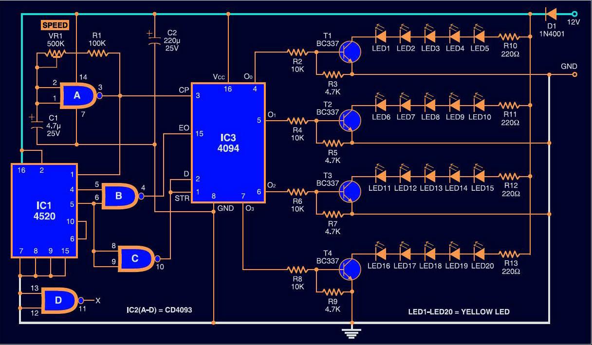
During poor visibility, i.e., when there is fog, or at dawn or dusk, or when your vehicle gets stalled on a lonely stretch of a highway, this flashing light will provide safety and attract the attention of people to help you out. It uses highbrightness yellow LEDs. 

  The circuit uses a dual binary counter CD4520, quadruple 2-input NAND schmitt trigger CD4093, 8-stage shift-and-store bus register CD4094 and some descrete components. An oscillator is built around gate A, whose frequency can be varied through preset VR1 when required. The output of the oscillator is fed to IC1 and IC3. When the circuit is switched on, the oscillator starts oscillating, the counter starts counting through IC1 and the data is shifted on positive-going clock through IC3. As a result, the four groups of LEDs flash one by one.
  All the LEDs will then glow for some time and switch off for some time, and the cycle will repeat. Input pins 12 and 13 of the unused gate D must be tied to ground and pin 11 left open. Preset VR1 should be of cermet type and used to change the flashing rate of each group of LEDs. The circuit works off regulated 12V. Assemble it on a general-purpose PCB and house suitably.

Twitter Delicious Facebook Digg Stumbleupon Favorites More