Showing posts with label Infrared Based Circuits. Show all posts

Monday, June 27, 2011

Universal IR Remote Control


Here is a circuit which can switch on and switch off any appliance with the help of a common type of infra-red remote control (transmitter). 
click to enlarge

This circuit senses the IR pulse and then controls the appliance accordingly. The circuit functions such that a short pulse from the remote tran- smitter switches on the triac (and the load) while a longer pulse switches off the triac as also the load. The circuit is built around hex inverter IC CD 4049. When the infra-red pulse is received by the sensor, its output (Note: Here VR1 denotes the in-circuit resistance of preset VR1.) The output of multivibrator is fed to the base of current amplifier 2N3055 via resistor R2 (1kilo-ohm). The brakelight bulb is connected in series with the collector of 2N3055. The flashing rate of this bulb is adjusted by 100k preset (VR1). 
Transistor 2N3055 may get heated due to high current switching action; hence a small heatsink, similar to the type used in television power supply, is recommended. The category of 2-wheelers which do not have a battery, can use the bridge rectifier circuit shown here. Several designs of round, square and rectangular reflectors are available which may be used in conjunction with any suitable 12V bulb with proper rating (around 20 watts). However, if flashing of the brake- light affects intensity of headlight bulb, reduce the rating of brakelight bulb to 10 watts.

IR Headphone


Using this low-cost project one can reproduce audio from TV without disturbing others. It does not use any wire connection between TV and headphones. In place of a pair of wires, it uses invisible infrared light to transmit audio signals from TV to headphones. Without using any lens, a range of up to 6 metres is possible. Range can be extended by using lenses and reflectors with IR sensors comprising transmitters and receivers.
click to enlarge

 IR transmitter uses two-stage transistor amplifier to drive two series-connected IR LEDs. An audio output transformer is used (in reverse) to couple audio output from TV to the IR  transmitter. Transistors T1 and T2 amplify the audio signals received from TV through the audio transformer. Lowimpedance output windings (lower gauge or thicker wires) are used for connection to TV side while high-impedance windings are connected to IR transmitter.  
This IR transmitter can be powered from a 9-volt mains adapter or battery. Red LED1 in transmitter circuit functions as a zener diode (0.65V) as well as supply-on indicator. IR receiver uses 3-stage transistor amplifier. The first two transistors (T4 and T5) form audio signal amplifier while the third transistor T6 is used to drive a headphone. Adjust potmeter VR2 for max. clarity.

Direct photo-transistor towards IR LEDs of transmitter for max. range. A 9-volt battery can be used with receiver for portable operation.

Remote control Timer


This infrared remote control timer can be used to turn an appliance on/off for a period of 0.11 second to 110.0 seconds. 
click to enlarge

The circuit comprises two sections, namely, the transmitter section and the receiver section.
Fig. 1 shows the IR transmitter section. The astable multivibrator NE555 (IC1) is used to  enerate a 10kHz modulated IR signal. The output of IC1 is connected to the base of pnp transistor T1 via resistor R2. Two infrared LEDs (IR1 and IR2) are connected in series between the collector (via resistor R3) and ground. When switch S1 is pressed, the IR LEDs transmit the modulated IR signal of 10-11 kHz. This frequency can be changed with the help of VR1 potmeter.
  In the receiver section shown in Fig. 2, two photodiodes (IR3 and IR4) receive the IR sign l transmitted by the IR transmitter. Transistors T2 and T3 amplify the weak signal. The amplified signal is filtered by capacitors C6 and C7. The amplified and filtered signal is now fed to the inverting input pin 2 of op-amp IC2 (IC 741). The output of IC2 is further connected to trigger pin 2 of timer NE555 (IC3) that is used as a monostable multivibrator whose frequency may be varied with the help of potmeter VR3.
  When switch S1 of the transmitter is pressed, the modulated IR rays are generated, which are received by photodiodes in the receiver section and amplified by the amplifier circuit. The output of op-amp goes low to trigger the monostable. Then high output at pin 3 of IC3 activates the twochangeover relay RL via transistor T3 (BC548) for a preset time.
  The on/off time can be set in the timer with the help of VR3 and C0. Switch S2 is used to reset the monostable. If you want to turn the appliance on for a preset time, connect the appliance via relay RL(a). On the other hand, if you want to turn the appliance off for a preset time, connect the appliance via relay RL(b). The timer can be reset by pressing reset switch S2.
 The circuit works up to 3 metres without using any focusing lens. However, you can increase the operating range by using focusing lens

Remote control For Home Appliance


Connect this circuit to any of your home appliances (lamp, fan, radio, etc) to make the appliance turn on/off from a TV, VCD or DVD remote control. The circuit can be activated from up to 10 metres.
click to enlarge

  The 38kHz infrared (IR) rays generated by the remote control are received by IR receiver module TSOP1738 of the circuit. Pin 1 of TSOP1738 is connected to ground, pin 2 is connected to the power supply through resistor R5 and the output is taken from pin 3. The output signal is amplified by transistor T1 (BC558). The amplified signal is fed to clock pin 14 of decade counter IC CD4017 (IC1). Pin 8 of IC1 is grounded, pin 16 is connected to Vcc and pin 3 is connected to LED1 (red), which glows to indicate that the appliance is ‘off.’
 The output of IC1 is taken from its pin 2. LED2 (green) connected to pin 2 is used to indicate the ‘on’ state of the appliance. Transistor T2 (BC548) connected to pin 2 of IC1 drives relay RL1. Diode 1N4007 (D1) acts as a freewheeling diode. The appliance to be controlled is connected between the pole of the relay and neutral terminal of mains. It gets connected to live terminal of AC mains via normally opened (N/O) contact when the relay energises.

Sunday, June 19, 2011

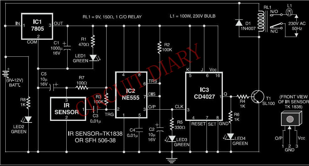
IR Remote Switch


Imagine the convenience of selecting TV channels using your remote and then pointing the same remote to your switchboard to switch on/off the fan or the tubelight. Here is a simple circuit to remotely switch on/off any electrical device through a relay using the normal TV/ VCR/VCP/VCD remote control unit. It works up to a distance of about 10 metres.
click to enlarge

 The circuit is built around a 3-pin IR IC receiver (Siemens SFH-506-38 or equivalent) that can detect 38kHz burst frequency  generated by a TV remote.
 The output pin of IR sensor goes low when it detects IR light, triggering the monostable (1-second) built around timer NE555. The output of the mono toggles the J-K flip flop, whose Q output drives the relay through SL100 npn transistor (T1).
 LED2, LED3, and LED4 are used to display the status of each output stage during circuit operation. Back-EMF diode D5 is used for protection. Transistor T1 is configured as an open-collector output device to drive the relay rated at 12V DC.
 The circuit draws the power from voltage regulator 7805. Capacitor C5 is soldered close to the IR sensor’s pins to avoid noise and false triggering. Capacitor C3 and resistor R3 also avoid false triggering of  monostable NE555. The monostable acts as a 1-second hysterisis unit to restrict the flipflop from getting retriggered within one second. To activate any other 12V logic device, use the output across the relay coil terminals.

INFRARED ELECTRONIC SHOOTING GAME


click to enlarge
Just trigger an infrared electronic gun and there goes one invisible bullet hitting the bull’s eye, if timed properly. The circuit is very simple, inexpensive and easy to construct. The game offers hours of fun and excitement.
  The target screen consists of a number of LEDs moving rapidly in a circular fashion. All the LEDs are red except one—the real target located in centre of the screen which is green. When a shot is fired by triggering the gun, all LEDs go off except one. If it happens to be the target (green LED) then you have made a hit which is indicated by lighting up of another green LED accompanied by a pleasing  musical tone. After a short delay the game restarts automatically.

click to enlarge

   Infrared gun (transmitter) for this electronic game is built around IC1 timer (NE555) wired as an astable multivibrator with a centre frequency of about 35 kHz. The frequency is determined by the timing components comprising resistors R1 and R2 and capacitor C2. When push-to-on trigger switch S1 is pressed, the astable multivibrator starts modulating the infrared beam with short pulses (See output waveform). The whole circuit can be enclosed in a toy gun for giving it a professional look as illustrated in the figure. The infrared LED has to be fitted with a suitable reflector to ensure good sensitivity.  
 When power switch S2 in the receiver is turned on, astable multivibra-tor wired around IC3 (NE555) generates clock pulses which are fed to clock input (pin 14) of decade counter IC4 (CD4017B). This IC has ten outputs, and each one goes high sequentially on the rising edge of successive clock pulse. As a result, LEDs connected to the output appear to move from one to the other rapidly. You would notice that only nine outputs are used for driving LEDs. The tenth output (Q9) at pin 11 is connected to reset pin 15.
 When gun is fired, infrared bursts are received by the integrated infrared module and its output at pin 2 goes low. The resulting falling edge triggers monostable IC2 and its output (pin 3) goes high.
 This makes clock enable (CE) pin 13 of IC4 to go high (normally held at a low potential via resistor R8) and it starts counting. When mono pulse ends, and if the last lit LED happens to be the target LED then both inputs of NAND gate N1 become high. As a result, the output of gate N2 also goes high. This in turn switches on transistor T2; thereby the ‘HIT’ LED lights up and the buzzer also sounds. At the end of the mono pulse period (about 5 sees), decided by resistor R5 and capacitor C5, the mono IC2 is again ready to receive another trigger pulse.
  Assembly and component layout is not very critical. The circuit may be assembled on a veroboard using IC sockets. A well regulated power supply is required for powering the unit. In place of the IR transmitter it is also possible to make use of the remote control used for TVS or VCPs/VCRs.

INFRARED TOY CAR MOTOR CONTROLLER


This add-on circuit enables remote switching on/off of battery-operated toy cars with the help of a TV/ video remote control handset operating at 30–40 kHz.
cilck to enlarge

 When the circuit is energized from a 6V battery, the decade counter CD4017 (IC2), which is configured as a toggle flip-flop, is immediately reset by the power-onreset combination of capacitor C3 and resistor R6. LED1 connected to pin 3 (Q0) of IC2 via resistor R5 glows to indicate the standby condition. In standby condition, data output pin of the integrated infrared receiver/demodulator (SFH505A or TSOP1738) is at a high level (about 5 volts) and transistor
T1 is ‘off’ (reverse biased). The monostable wired around IC1 is inactive in this condition.
  When any key on the remote control handset is depressed, the output of the IR receiver momentarily transits through low state and transistor T1 conducts. As a result, the monostable is triggered and a short pulse is applied to the clock input (pin 14) of IC2, which takes Q1 output (pin 2) of IC2 high to switch on motor driver transistor T2 via base bias resistor R7 and the motor starts rotating continously (car starts running). Resistor R8 limits the starting current.  
 When any key on the handset is depressed again, the monostable is retriggered to reset decade counter IC2 and the motor is switched off. Standby LED1 glows again.
 This circuit can be easily fabricated on a general-purpose printed board. After construction, enclose it inside the toy car and connect the supply wires to the battery of the toy car with right polarity. Rewire the DC motor connections and fix the IR receiver module in a suitable location, for example, behind the front glass, and connect its wires to the circuit board using a short 3-core ribbon cable/shielded wire.
 Note. Since the circuit uses modulated infrared beam for control function, ambient light reflections will not affect the circuit operation. However, fluorescent tubelights with electronic ballasts and CFL lamps may cause malfunctioning of the circuit.

Twitter Delicious Facebook Digg Stumbleupon Favorites More