Showing posts with label Miscellaneous. Show all posts

Monday, June 27, 2011

Audio Perimeter Monitor


This circuit is intended for audio surveillance of an unattended area, examples being a back garden or open space. It can be used to listen for wildlife or just as an extra pair of ears. 
Click to enlarge

Using a single cable such as speaker wire or doorbell cable, this circuit can be remotely positioned, for example, at the bottom of a garden or garage, and used to detect all sound in that area.  The cable can be buried in a hosepipe or duct and is concealed out of sight. The mic is an ordinary dynamic mic insert and should be housed in a waterproof enclosure with the rest of the circuit. The mic output is amplified by the two transistors, the output is fed down the cable via the 220u capacitor. Here, it has a dual purpose of preventing the DC supply from upsetting the bias of the circuit, and also allowing the smaller ac audio output to pass down the line. At the power supply, the audio is recovered by the 10k preset and 220u capacitor. It is used to feed a small audio amplifier (such as the 2watt design) shown earlier on this site. 

Motor Speed controler

 
The circuits shown below are a few of many suggested circuits as published by SCR and TRIAC manufacturers and cannot be construed as beeing the exact application for your requirements and I cannot be held responsible for their use and end results . 

click to enlarge

It is suggested that the subject of TRIAC and SCR as well as motor drive control systems be researched before making a final decision as to the application of these control circuits .
For satisfactory and safe results, knowing the exact type of motor you wish to control is of prime importance and all data available should be obtained before you contemplate to add any drive control circuits . Mount all SCR's and Triac on heatsink . Use current rated stranded wiring as required .
If you cannot find the SCR's and TRIAC's suggested in the circuits you may be able to find a substitute following this link Cross References
Some links to SCR's,TRiac's and motor control application notes:

Thyristors
Application Notes
Triac Data
NTE Triac Selection
NTE SCR Selection
You can use a transformer with up to 12 amps output current with corresponding fuse value . Use No.12-14 stranded wiring to battery connection with heavy duty clips .
Mount Rectifiers and SCR's on heatsink . You can use a mA meter with a shunt resistor . See
Metering a power supply .
Note The rectifiers and SCR's value as quoted can be changed to lesser values as required for lower current output .


Automatic Room power Controler


An ordinary automatic room power control circuit has only one light sensor. So when a person enters the room it gets one pulse and the lights come ‘on.’ When the person goes out it gets another pulse and the lights go ‘off.’ But what happens when two persons enter the room, one after the other? It gets two pulses and the lights remain in ‘off’ state. 
click to enlarge

 The circuit described here overcomes the above-mentioned problem. It has a small memory which enables it to  utomatically switch ‘on’ and switch ‘off’ the lights in a desired fashion. The circuit uses two LDRs which are placed one after another (separated by a istance of say half a metre) so that they may separately sense a person going into the room or coming out of the room. Outputs of the two LDR sensors, after processing, are used in conjunction with a bicolour LED in such a fashion that when a person gets into the room it emits green light and when a person goes out of the room it emits red light, and vice versa. These outputs are simultaneously applied to two counters.
One of the counters will count as +1, +2, +3 etc when persons are coming into the room and the other will count as -1,-2, -3 etc when persons are going out of the room. These counters make use of Johnson decade counter CD4017 ICs. The next stage comprises two logic ICs which can combine the outputs of the two counters and determine if there is any person still left in the room or not. Since in the circuit LDRs have been used, care should be taken to protect them from ambient light. If desired, one may use readily available IR sensor modules to replace the LDRs. The sensors are installed in such a way that when a person enters or leaves the room, he intercepts the light falling on them sequentially—one after the other.
 When a person enters the room, first he would obstruct the light falling on LDR1, followed by that falling on LDR2. When a person leaves the room it will be the other way round. In the normal case light keeps falling on both the LDRs, and as such their resistance is low (about 5 kilo-ohms). As a result, pin 2 of both timers (IC1 and IC2), which have been configured as monostable flip-flops, are held near the supply voltage (+9V).
 When the light falling on the LDRs is obstructed, their resistance becomes very high and pin 2 voltages drop to near ground potential, thereby triggering the flip-flops. Capacitors across pin 2 and ground have been added to avoid false triggering due to electrical noise.
 When a person enters the room,  LDR1 is triggered first and it results in triggering of monostable IC1. The short output pulse immediately charges up capacitor C5, forward biasing transistor pair T1-T2. But at this instant the collectors of transistors T1 and T2 are in high impedance state as IC2 pin 3 is at low potential and diode D4 is not conducting.
But when the same person passes LDR2, IC2 monostable flip-flop istriggered. Its pin 3 goes high and this potential is coupled to transistor pair T1-T2 via diode D4. As a result transistor pair T1-T2 conducts because capacitor C5 retains the charge for some time as its discharge time is controlled by resistor R5 (and R7 to an extent). Thus green LED portion of bi-colour LED is lit momentarily.
 The same output is also coupled to IC3 for which it acts as a clock. With entry of each person IC3 output (high state) keeps advancing. At this stage transistor pair T3-T4 cannot conduct because output pin 3 of IC1 is no longer positive as its output pulse duration is quite short and hence transistor collectors are in high impedance state.
 When persons leave the room, LDR2 is triggered first, followed by LDR1.  Since the bottom half portion of circuit is identical to top half, this time, with the departure of each person, red portion of bicolour LED is lit momentarily and output of IC4 advances in the same fashion as in case of IC3.
 The outputs of IC3 and those of IC4 (after inversion by inverter gates N1 through N4) are ANDed by AND gates (A1 through A4) and then wire ORed (using diodes D5 through D8). The net effect is that when persons are entering, the output of at least one of the AND gates is high, causing transistor T5 to conduct and energise relay RL1. The bulb connected to the supply via N/O contact of relay RL1 also lights up.
 When persons are leaving the room, and till all the persons who entered the room have left, the wired OR output continues to remain high, i.e. the bulb continues to remains ‘on,’ until all persons who entered the room have left.
 The maximum number of persons that this circuit can handle is limited to four since on receipt of fifth clock pulse the counters are reset. The capacity of the circuit can be easily extended to handle up to nine persons by removing the connection of pin 1 from reset pin (15) and utilising Q1 to Q9 outputs of CD4017 counters. Additional inverters, AND gates and diodes will, however, be required.

Intercom communication


The circuit presented here can be used for connecting two telephones in parallel and also as a 2-line intercom.
Usually a single telephone is connected to a telephone line. If another telephone is required at some distance, a parallel line is taken for connecting the other telephone. In this simple parallel line operation, the main problem is loss of privacy besides interference from the other phone. This problem is obviated in the circuit presented here.
 Under normal condition, two telephones (telephone 1 and 2) can be used as intercom while telephone 3 is connected to the lines from exchange. In changeover mode, exchange line is disconnected from telephone 3 and gets connected to telephone 2.
 For operation in intercom mode, one has to just lift the handset of phone 1 and then press switch S1. As a result, buzzer PZ2 sounds. Simultaneously, the side tone is heard in the speaker of handset of phone 1. The person at phone 2 could then lift the handset and start conversation. Similar procedure is to be followed for initiation of the conversation from phone 2 using switch S2.
  In this mode of operation, a 3-pole, 2-way slideswitch S3 is to be used as shown in the figure. In the changeover mode of operation switch S3 is used to changeover the telephone line for use by telephone 2.
click to enlarge

The switch is normally in the intercom mode and telephone 3 is connected to the exchange line. Before changing over the exchange line to telephone 2, the person at telephone 1 may inform the person at telephone 2 (in the intercom mode) that he is going to changeover the line for use by him (the person at telephone 2). As soon as changeover switch S3 is flipped to the other position, 12V supply is cut off and telephones 1 and 3 do not get any voltage or ring via the ring-tone-sensing unit.
  Once switch S3 is flipped over for use of exchange line by the person at telephone 2, and the same (switch S3) is not flipped back to normal position after a telephone call is over, the next  telephone call via exchange lines will go to telephone 2 only and the ring-tonesensing circuit will still work. This enables the person at phone 3 to know that a call has gone through. If the handset of telephone 3 is lifted, it is found to be dead. To make telephone 3 again active, switch S3 should be changed over to its normal position.

Remote control Timer


This infrared remote control timer can be used to turn an appliance on/off for a period of 0.11 second to 110.0 seconds. 
click to enlarge

The circuit comprises two sections, namely, the transmitter section and the receiver section.
Fig. 1 shows the IR transmitter section. The astable multivibrator NE555 (IC1) is used to  enerate a 10kHz modulated IR signal. The output of IC1 is connected to the base of pnp transistor T1 via resistor R2. Two infrared LEDs (IR1 and IR2) are connected in series between the collector (via resistor R3) and ground. When switch S1 is pressed, the IR LEDs transmit the modulated IR signal of 10-11 kHz. This frequency can be changed with the help of VR1 potmeter.
  In the receiver section shown in Fig. 2, two photodiodes (IR3 and IR4) receive the IR sign l transmitted by the IR transmitter. Transistors T2 and T3 amplify the weak signal. The amplified signal is filtered by capacitors C6 and C7. The amplified and filtered signal is now fed to the inverting input pin 2 of op-amp IC2 (IC 741). The output of IC2 is further connected to trigger pin 2 of timer NE555 (IC3) that is used as a monostable multivibrator whose frequency may be varied with the help of potmeter VR3.
  When switch S1 of the transmitter is pressed, the modulated IR rays are generated, which are received by photodiodes in the receiver section and amplified by the amplifier circuit. The output of op-amp goes low to trigger the monostable. Then high output at pin 3 of IC3 activates the twochangeover relay RL via transistor T3 (BC548) for a preset time.
  The on/off time can be set in the timer with the help of VR3 and C0. Switch S2 is used to reset the monostable. If you want to turn the appliance on for a preset time, connect the appliance via relay RL(a). On the other hand, if you want to turn the appliance off for a preset time, connect the appliance via relay RL(b). The timer can be reset by pressing reset switch S2.
 The circuit works up to 3 metres without using any focusing lens. However, you can increase the operating range by using focusing lens

Human Week Reminder


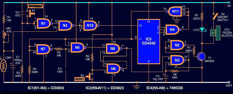
This circuit reminds you of all the important tasks that are due on a specific day every week. So be it returning your library book, switching on your favourite TV programme, putting the dustbin out or cleaning the car, it automatically flashes an LED that very day to alert you of something to be done. The LED keeps flashing until you press the reset button.   

The circuit consumes very little power. The circuit can count the days. The rising of the Sun is detected by a light dependent resistor (LDR1). When the sun rises, the ambient light level reduces the resistance of LDR1. The voltage level at pin 13 of gate N4 goes low. Since the other input (pin 12) of gate N4 is high, its output also goes high. This is inverted by gate N10 whose output goes low to make counter IC3 advance by one count. This way each day is counted. Similarly, the counter advances by one every morning until it counts seven days.
  In the morning of the seventhday, all the inputs of gate N9 become high, making its output low. The low output of gate N9 is inverted by gate N11 to trigger the pulse generator built around gates N5 and N7, and it produces a short-duration pulse to trigger the flip-flop built around gates N6 and N8. As a result, the output of the flip-flop goes high to enable the astable multivibrator built around gate N3. The astable multivibrator produces 2Hz frequency to flash LED1 as a reminder. LED1 flashes until you press reset switch S2 momentarily.
 When the enable input (pin 8) of gate N3 is low, the output of the astable multivibrator remains high. Gate N2 inverts this high level into low and the transistor does not conduct. So LED1 doesn’t flash when the astable multivibrator is disabled.  Counter IC3 also resets when the pulse generator triggers because its reset pin 11 is connected to the output of gate N11. When the counter IC3 resets, its output becomes low and it’s ready to begin day counting for the next week.
  Suppose you require a reminder for four days. Then first cover the sensor  and press increment switch S1 thrice momentarily and leave it. Now your reminder (flashing of LED1) starts after four days.
 Assemble the circuit on a general purpose PCB and enclose in a suitable cabinet. After assembling the circuit, proper setting is required.First of all, switch on the power. LED1 flashes. Press switch S2 to stop it from flashing. Cover LDR1 and press S1 several times until LED1 flashes again. The counter is now set at a count of 0 and is ready to start weekdays counting. Press S2 to stop flashing.
 Do not uncover the sensor immediately after pressing S2. Else, the counter will register arrival of the next day and LED1 will flash after six days. To make it flash weekly on a particular day, keep the LDR1 in dark until night.

Highway Alert signal Generator


Here is a signal lamp for safe highway driving. The lamp automatically emits brilliant tricolour light when a vehicle approaches the rear side of your vehicle. It emits light for 30 seconds that turns off when the approaching vehicle overtakes. The ultra-bright blue, white and red LEDs of the signal lamp emit very bright light to alert the approaching vehicle’s driver even during the day, giving additional safety during night, or when you need to stop your vehicle on side of the highway.
click to enlarge

 The circuit saves considerable battery power. The circuit is built around two timer ICs NE555 (IC1 and IC2). IC1 is designed as a standard monostable, while IC2 is designed as an astable. Darlington phototransistor L14F1 (T1) is used as a photosensor to activate the monostable. The collector of phototransistor T1 is connected to trigger pin 2 of IC1, which is normally kept high by resistor R1.
  When headlight from an approaching vehicle illuminates the phototransistor, it conducts to give a short pulse to IC1, and the output of IC1 goes high for a period determined by resistor R2 and capacitor C1. The output of IC1 is fed to the base of transistor T2 via resistor R3. Transistor T2 conducts to drive transistor T3 and its collector goes high to take reset pin 4 of IC2 to high level. This activates astable IC2, which switches on and off the LED chain alternately. The intermittent flashing of LEDs gives a beautiful tricolour flashlight effect.
 The circuit can be easily constructed on a small piece of general-purpose PCB. Fig. 2 shows the bottom and front views of Darlington phototransistor L14F1. The proposed arrangement of LEDs, which are soldered in a circular fashion on a general purpose PCB, is shown in Fig. 3. Use a circular reflector for the LEDs to get brighter light. Fix the LED arrangement on the rear side of your vehicle, and the phototransistor where it is illuminated directly by the headlight of the approaching vehicle. 12V DC supply to the circuit, can be provided by your vehicle battery with proper polarity.

Human Heraing Aid


Commercially available hearing aids are quite costly. Here is an inexpensive hearing aid circuit that uses just four transistors and a few passive components. 
click to enlarge

 On moving power switch S to ‘on’ position, the condenser microphone detects the sound signal, which is amplified by transistors T1 and T2. Now the amplified signal passes through coupling capacitor C3 to the base of transistor T3. The signal is further amplified by pnp transistor T4 to drive a lowimpedance earphone. Capacitors C4 and C5 are the power supply decoupling capacitors.
 The circuit can be easily assembled on a small, general-purpose PCB or a Vero board. It operates off a 3V DC supply. For this, you may use two small 1.5V cells. Keep switch S to ‘off’ state when the circuit is not in use. To increase the sensitivity of the condenser microphone, house it inside a small tube.

Digital Dice


The digital dice presented here acts just like a normal dice. It has six faces (refer Fig. 2) like the normal dice and uses four different logic gate combinations to bring out the six faces of the dice. At the heart of the circuit is a 14- stage ripple-carry binary counter IC CD4060BC (IC1) with built-in oscillator. The logic section is designed around CMOS quad 2-input NOR gate IC CD4001BC (IC2) and quad 2-input NAND gate IC CD4011BC (IC3). The display section is formed by a group of seven LEDs. 
click to enlarge

The circuit is divided into three sections: counter, logic and display. The counter section is built around binary counter IC CD4060BC (IC1). The counter frequency (f) is decided by the in-built oscillator formed by resistor R1 and capacitor C1 as follows: f=1/2.2R1C1. Here, the frequency is fixed at around 2056 Hz. Only the first three outputs of the counter (designated as A, B and C, respectively) have been used in the circuit.
 The counter is designed to reset at the sixth count (110) as only six counts are required for operation. This is done with the help of diodes D1 and D2 and resistor R3, which are connected such that they generate an AND logic. From the table it can be noticed that at the sixth count, the counter outputs A and B hold logic 1 simultaneously for the first time,so by ANDing A and B outputs you can give logic 1 to the reset terminal of the counter at the sixth count, thereby resetting the counter.
 LED2 and LED5 always glow at the same count, as do LED1 and LED6, and LED3 and LED4. Using these three pairs of LEDs and LED7, four logical combinations have been made in the circuit. LED1 and LED6 glow at all counts, except ‘0’ and ‘1.’ Further, it can be noticed that they glow when ‘A’ or ‘B’ is high, hence a NOR gate whose output is A+B according to Boolean algebra will perform the job of operating these LEDs.
 LED3 and LED4 glow at all counts, except for the first three counts, i.e., they glow when either A, or B and C are high. This logic function can be obtained by using an OR gate and an AND gate, but since we are using only NAND and NOR gates in the circuit we make use of two NAND gates and a NOR gate (with A+BC output) to perform this function. LED2 and LED5 glow only at the first and fifth counts. In other words, they glow only when the complement of B and C outputs goes high. This function can be obtained by using two NAND gates such that their output corresponds to the Boolean expression BC or B+C according to De Morgan’s theorem.
  LED7 glows at even counts like 0, 2 and 4. In other words, it glows when the C output is low. This function can be achieved easily by inverting the C output twice using the remaining two NAND gates. The output will also be buffered by these two inverter gates.
 The display section comprises seven LEDs. LED1 and LED6 have common cathodes, as do LED2 and LED5, and LED3 and LED4. The anodes of all the LEDs are tied together to the positive terminal of the battery via resistors R4 through R10, respectively.
 When you place your finger on the touch pad, the oscillator starts oscillating. The counter will start counting at the rate of 2056 Hz and all the LEDs of the display section will appear to glow simultaneously due to the high counter frequency. This high-frequency counting will make the dice foolproof. When you remove your finger from the touch pad, the counter will stop counting and the display section will show any one of the six possible faces with a probability of 1/6. The entire circuit can be powered by a 9V battery as the inbuilt oscillator of the counter IC will not work properly below 7V. Use of CMOS ICs means less power consumption.
 The circuit can be constructed on a general-purpose PCB and housed inside a plastic case with the LEDs arraymounted on the top as shown in Fig. 2. The touch pad can be mounted beside the array.

Aquarium Temperature Indicator


A number of environmental factors including light and temperature affect fish culture. The temperature of water has profound effect because fish cannot breed above or below the critical temperature limits. Temperature between 24°C and 33°C is found to be the best to induce spawning in fishes. This particular temperature range is also necessary for the healthy growth of nursery fish fries (young fishes). Rise of water temperature due to sunlight may adversely affect the fish rearing process.
click to enlarge

 The circuit of aquatic probe described here can monitor the temperature of water and indicate the rise in temperature through audiovisual indicators. A readily available signal diode 1N34 is used in the circuit as the temperature sensing probe. The resistance of the diode depends on the temperature in its vicinity. Typically, the diode can generate around 600 mV when a potential difference is applied to its terminals. For each degree centigrade rise in temperature, the diode generates 2mV output voltage. That is, at 5°C, it is 10 mV, which rises to 70 mV when the temperature is 35°C. This property is exploited in the circuit to sense the temperature variation in aquarium water. Fig. 1 shows the circuit diagram of the aquarium probe.
 Since the output from the diode sensor is too low, a high-gain inverting DC amplifier is used to amplify the voltage. CA3140 (IC1) is the CMOS version op-amp that can operate down to zero-volt output. The highest output available from IC1 is 2.25V less than the input voltage at pin 7. With resistor R4 and VR2, the variation in diode voltage can be amplified to the required level. Resistor R1 restricts current flow through diode D1 and preset VR1 (1-kilo-ohm) sets the input voltage at pin 3. IC3 (7805) provides regulated 5 volts to the inputs of IC1, so that the input voltage is stable for accurate measurement of temperature.
 The output from IC1 is fed to display driver LM3915 (IC2) through preset VR3 (50-kilo-ohm). With careful adjustments, the wiper of VR3 can provide 0-400 millivolts to the input of IC2. The highly sensitive input of IC2 accepts as low as 50 mV if the reference voltage at its pin 7 is adjusted using a variable resistor. To increase the sensitivity of IC2, preset VR4 is connected at one end to ‘reference voltage end’ pin 7 and its wiper is connected to ‘high end’ pin 6 of the internal resistor chain.  
 When approximately 70 mV is provided to the input of IC2 by adjusting preset VR3, LED1 (green) lights up to indicate that the temperature is  approximately 35°C, which is the crossing point. When the input receives 100 mV, LED2 (red) lights up to indicate approximately 50°C. Finally, the buzzer starts beeping if the input receives 130 mV corresponding to a temperature of 65°C. In short, LEDs and the buzzer remain standby when the temperature of the water is below 35°C normal). With each step increase of 30 mV in the input (corresponding to 15°C rise in temperature), LEDs and the buzzer become active.
 Pin 16 of IC2 is used to drive the piezobuzzer through transistor T1. When pin 16 of IC2 becomes low, T1 conducts to beep the piezobuzzer. Resistor R7 keeps the base of transistor T1 high to avoid false alarm. IC4 provides regulated 9V DC to the circuit.
 Assemble the circuit on a common PCB and enclose in a suitable case. Glass signal diode D1 is immersed in water to sense the temperature of water. Its leads should be coated with enamel paint to avoid shorting in water. Alternatively, enclose the diode in a small glass tube or test tube having sufficient internal space to fit the diode as shown in Fig. 2. Make the sensor assembly waterproof using wax.
 Take care while calibrating and setting the circuit. With 5V DC supply to diode D1 and an ambient temperature of about 35°C, D1 generates around 70 mV. Adjust VR3 until the voltage in its wiper increases to 70 mV, so that the input of IC2 (pin 5) receives 70 mV corresponding to the diode output voltage at 35°C. At this stage, green LED1 should turn on. If it doesn’t, adjust VR4 until LED1 just lights up. Immerse the diode in temperature-adjusted hot water (35°C) and adjust VR3 and VR4 until green LED1 lights up. Increase the water temperature to 50°C by adding hot water. Now red LED2 will glow. At this position, the voltage at pin 6 of IC1 will be around 100 mV. When the temperature of water increases further to 65°C, the buzzer starts beeping. After calibration, immerse the diode assembly in the aquarium tank just below the water surface and fix it permanently to avoid floating.

Sunday, June 26, 2011

Voltage Based Controller For Switches


 Here’s a simple circuit for controlling four switches from a distance through just a pair of wires. In the circuit, the inverting inputs (pin 2) of operational amplifiers IC1 through IC4 are set to refrence voltages of +12V, +9V, +6V, and +3V, respectively, through a chain of four 1k resistors (R1 through R4).
The reference voltage (VREF) can be simply calculated by the following relationship:
click to enlarge


The non-inverting inputs (pin 3) of the four op-amps ( IC1 through IC4) are tied together and connected to a pair of wires that provide +3V to +12V input voltage for controlling the switches.
Four 12V, 200-ohm, singlechangeover relays are connected to four BC548 relay driver transistors (T1 through T4) via resistors R5 through R8, respectively.
 These relays energise depending on the voltage present at the controlling volt- Total applied voltage×Resistance across reference voltage input terminal; for example, relay RL4 energises when controlling voltage input of +3V is available at non-inverting pin 3 of IC4. Four electrical equipment can be connected to the terminals of the relays through the 220V AC, 50Hz mains.

Solar Panel Charger


You can save on your electricity bills by switching to alternative sources of power. The photovoltaic module or solar panel described here is capable of delivering a power of 5 watts. At full sunlight, the solar panel outputs 16.5V.  It can deliver a current of 300-350 mA. Using it you can charge three types of batteries: lead acid, Ni-Cd and Li-ion. The lead-acid batteries are commonly used in emergency lamps and UPS. 
click to enlarge

 The working of the circuit is simple. The output of the solar panel is fed via diode 1N5402 (D1), which acts as a polarity guard and protects the solar panel. An ammeter is connected in series between diode D1 and fuse to measure the current flowing during charging of the batteries. As shown in Fig. 1, we have used an analogue multimeter in 500mA range. Diode D2 is used for protection against reverse polarity in case of wrong connection of the lead-acid battery. When you connect wrong polarity, the fuse will blow up.
 For charging a lead-acid battery, shift switch S1 to ‘on’ position and use connector ‘A.’ After you connect the battery, charging starts from the solar panel via diode D1, multimeter and fuse. Note that pulsating DC is the best for charging lead-acid batteries. If you use this circuit for charging a lead-acid battery, replace it with a normal pulsating DC charger once a week. Keep checking the water level of the leadacid battery. Pure DC voltage normally leads to deposition of sulphur on the plates of lead-acid batteries.
 For charging Ni-Cd cells, shift switches S1 and S3 to ‘on’ position and use connector ‘B.’ Regulator IC 7806 (IC1) is wired as a constantcurrent source and its output is taken from the middle terminal (normally grounded). Using this circuit, a constant current goes to Ni-Cd cell for charging. A total of four 1.2V cells are used here. Resistor R2 limits the charging current.
  For charging Li-ion battery (used in mobile phones), shift switches S1 and S2 to ‘on’ position and use connector ‘C.’ Regulator IC 7805 (IC2) provides 5V for charging the Li-ion battery. Using this circuit, you can charge  a 3.6V Li-ion cell very easily. Resistor R3 limits the charging current.
  Fig. 2 shows the circuit for a small LED-based lamp. It is simple and lowcost. Six 10mm white LEDs (LED2 through LED7) are used here. Just connect them in parallel and drive directly by a 3.6V DC source. You can use either pencil-type Ni-Cd batteries or rechargeable batteries as the power source.
  Assemble the circuit on a generalpurpose PCB and enclose in a small box. Mount RCA socket on the front panel of  the box and wire RCA plug with cable for connecting the battery and LEDbased lamp to the charger.

Laptop Docking Station


You can easily convert your ordinary docking station into a smart electronic laptop docking station with antitheft alarm. 
click to enlarge

 The add-on sensor circuit required for this is built around IC CNY70 (IC1) and IC CD4060 (IC2) as shown in Fig. 1. IC CNY70 is an integrated reflectivetype opto-sensor that contains a phototransistor and an infrared LED. The LED emits infrared light and the transistor works as a receiver. The current flowing through the phototransistor depends on the intensity of the light detected. 
 IC CD4060 is a 14-stage ripple-carry binary counter. The counter is reset to zero by a gating positive voltage at the reset input independent of clock.
 Power supply to the circuit is derived from AC mains by using stepdown transformer X1. The transformer output is rectified by a full-wave bridge rectifier comprising diodes D1 through D4 and smoothed by capacitor C1. When power switch S1 is in ‘on’ position, the circuit gets power supply and power-on indicator LED1 lights up. At the same time, the mains socket also gets the AC mains supply. This mains socket can be used to connect the laptop charger and/or a desktop lamp, etc.
 Working of the circuit is simple. When the laptop is in the docking station, the phototransistor inside IC1 receives the IR light from the LEDreflected by the laptop surface. The phototransistor conducts to make reset pin 12 of IC2 high, so IC2 does not oscillate.
 When someone lifts up the laptop from the docking station, the phototransistor cuts off and pin 12 of IC2 goes low. As a result, IC2 starts oscillating. After a few seconds, delay pin 3 of IC2 goes high to drive transistor T1. The piezobuzzer starts beeping to raise an alert and the LED2 glows to indicate that someone has stolen the laptop from the dockyard.
 The simplicity of the circuit makesit ideal for construction on a small PCB. After completion of wiring, check the circuit for proper functioning of all the sections and enclose the unit in a suitable ABS case. Mount the finished unit beneath the docking station using small screws/double-sided glue pads so that the opto-sensor is exactly at the centre of the docking-station base plate. Refer Fig. 2 for the arrangement.
 If your laptop computer is black in colour, it will reflect far less IR light. You can overcome this drawbackattaching a white sticker suitably at the bottom of the laptop.
 Calibrate the circuit before first use. Set preset VR1 at the centre and place the laptop in the docking station. Now turn VR1 slowly until IC2 goes to standby (no-oscillation) mode. Then remove the laptop from the docking station, ensure that IC2 is enabled (pin 12 is low) and wait for the alarm sound. Repeat the process and adjust VR1 until you get the correct result. Note that the LED in the opto-sensor is permanently powered via resistor R2. Similarly, you are free to experiment with the values of IC2 timing components C5, R3 and R4 for increasing or decreasing the delay time.

Workbench

Typically, implementing and testing even a small circuit requires an elaborate setup that includes breadboards, a dual DC power supply, hookup wires, ICs and resistors of different values. This setup can be quite messy and difficult to clean up at the end of the experiment. Also, the power supply can make the setup non-portable. Here we present a mobile electronic workbench that makes it easier for you to assemble and test circuits.
click to enlarge

 This mobile workbench is useful for students in schools, colleges, research institutions and industries alike. It can be used conveniently wherever you want. It is also cost-effective andvery useful for giving demos. As the power is supplied by the batteries, the voltage is noise-free.
 Fig. 1 shows the circuit of the mobile electronic workbench. Two low-drop-out (LDO) regulators (one positive and the other negative) are used here to provide regulated +5V and -5V for digital ICs.
  When switch S1 is pushed to ‘on’ position, LEDs indicate the availability of voltages on the breadboard. When it is in ‘off’ position, the battery terminals connect to the sockets for charging the batteries. Apart from +6V and +5V supplies, you can also have a 12V source between +6V and -6V terminals.
 As shown in Fig. 2, the mobile workbench consists of a big melamine tray. At the centre of this tray, mount the breadboard. On the sides of the breadboard, stick two 6V, 4.5Ah maintenance-free lead-acid batteries (Batt.1 and Batt.2). On a wooden batten, mount two-pole, two-way toggle switch S1 and two fuses and two sockets symmetrically. Mount LED1 and LED2 on the sides of S1.
 If you do not want this mobile workbench on a breadboard, you can assemble it on a general-purpose PCB and enclose in a suitable cabinet. Fix LEDs and switch S1 on the front panel of the cabinet and the fuses at the back side of the box.
 In place of LM2990-5, you can use a 5.1V, 2W zener diode with 100- ohm, 2W series limiting resistor as shown in Fig. 3. During testing, we used a zener diode for negative 5V regulation instead of LM2990-5.

Sunday, June 19, 2011

Low-Cost PCO Billing Meter


The circuit presented here can be used in PCOs for displaying the actual bill. The comparative disadvantages of the presented circuit are as follows:

click to enlarge

1. The calculator used along with thiscircuit is required to be switched ‘on’ manually before making a call.
2. Certain manual entries have to be made in the calculator; for example, for a pulse rate of Rs 1.26, number 1.26 is to be entered after switching ‘on’ the calculator followed by pressing of ‘+’
button twice. However, possibility exists for automating these two functions by using additional circuitry.
  In telephony, on-hook condition is represented by existance of 48V to 52V across the line. Similarly, the off-hook condition is represented by the line voltage dropping to a level of 8V to 10V (depending upon the length of the local lead line (local loop) from telephone exchange to the subscriber’s premises as well as upon the impedance of telephone instrument). Handset is normally lifted either for dialing or in response to a ring.
  In the circuit shown in Fig. 1, when
the handset is off-hook, the optocoupler MCT2E (IC1) conducts and forward biases transistor T1, which, in turn, forward biases transistor T2 and energises relay RL1. In energized condition of relay, the upper set of relay contacts connects the positive supply rail to PLL (phaselocked loop) IC2 (LM567) pin 4, while the lower set of relay contacts couples the positive telephone lead to input pin 3 of LM567 via capacitor C1 and resistor R3.
 The negative telephone lead is pe- rmanently capacitively coupled to ground via capacitor C2. As soon as call matures, 16kHz tone pulses would be pumped into the telephone line by the telephone exchange at suitable intervals. This interval depends on the pulse rate of the place called and also the time of the day and whether it’s a working-day or holiday. On receipt of 16kHz pulse,output pin 8 of IC LM567 (which is tuned for centre frequency of 16 kHz) goes ‘low’ for the duration of the pulse. The output of IC2 is coupled via transistor T3 to optocoupler IC3. The output of this optocoupler is used to bridge the ‘=’ button on a calculator (such as Taksun make), which has the effect of pressing the ‘=’ button of the calculator.
 Considering that pulse rate for a specific town/time/day happens to be Rs 1.26 per pulse, then before maturity of the call one enters 1.26 followed by pressing of ‘+’ key twice. Now, if a total of ten billing pulses have been received from exchange for the duration of the call, then on completion of the call, the
calculator display would show 12.60. The telephone operator has to bill the customer Rs 14.60 (Rs 12.60 towards call charges plus Rs 2.00 towards service charges).
 For tuning of the PLL circuit around IC2, lift the handset and inject 16kHz tone across the line input points. Tune IC2 to centre frequency of 16 kHz with the help of preset VR1. Proper
tuning of the PLL will cause LED (D6) to glow even with a very lowamplitude 16kHz tone.
 Lab note. Arrangement used for simulating a 16kHz pulsed tone is shown in Fig. 2. Push-to-on switch is used for generation of fixed-duration pulse for modulating and switching on a 16kHz oscillator.rates, pulse codes, etc, readers are advised to go through the tariff rates and
pulse code information given in the beginning pages of telephone directories, such as MTNL.

Twitter Delicious Facebook Digg Stumbleupon Favorites More