Showing posts with label Safety and Security. Show all posts

Tuesday, June 28, 2011

Locker Security System


The project locker security system is aimed at protecting the offering box from robbery. The project is based on micro-controller AT89C51 and some associated components. The major advantage of this security system other than the available security system is that this sounds and alarm and calls to a predefined mobile number when an attempt of robbery is detected.
The mobile number can be of any persons managing the offering box and there is an option for a second mobile number to which the controller makes a second call at the time of robbery. The second mobile number can be the number of police station, so police will get notified and they can do the necessary actions immediately.  
As soon as the mobile calling section is finished by the controller it will generate an alarm. This alarm can only be disabled by using a secure password. So this security system has 3 levels of protection, password protection, call to predefined mobile number and an alarm.

click on image to enlarge
The heart of the circuit is the micro-controller AT89c51.
The power supply unit supplies regulated 5volt to the controller using lm7805. The transformer steps down the ac voltage to 12volt and rectifier diodes are used to convert 12volt ac to 12volt DC. This 12volt DC is then regulated to 5volt using LM7805.
 The controller on power up initializes the whole system. There is a power on reset circuit connected to the reset pin of the controller. So whenever power is switched on the controller resets.
 As per the program logic the controller first configures the LCD for displaying initializing data on the screen. Then the controller goes for controlling and monitoring other hardware peripherals.
A keypad is connected to the circuit for entering the password. The controller then checks this password correct or not. If it’s correct code the controller then actuates the relay for opening the door. When the controller opens the door it disables the tampering circuit sensors for eliminating false triggering. For closing the door a door close key is provided. When the door is closed the controller immediately enables the tamper circuitry.
If a wrong password is entered more than 3 times the controller calls to the predefined number and sounds an alarm.
The tamper is detected using a special custom made vibration sensor which works on Newton’s 3rd law of motion. The vibration sensors give an interrupt to the controller to indicate a tamper.
The LCD display displays the name of the security system and gives direction to the user to enter password and also notifies the user if the password is wrong and also gives indication about the calls during tamper.
The door of the offering box is made using an electronic sliding mechanism. On entering the correct password the correct password the controller actuates relay1 and relay 2. The relay outputs are connected to the motor of the sliding door mechanism. To open the door the motor is given a polarity at which it rotates in clockwise direction and to close the door the polarity of the motor is reversed.
The crystal used is 12 MHz; this gives clock to the micro-controller.
Transistor logic is used to actuate switches on the mobile phone for making calls. The transistor BC-547 is used as a switch mode. When the controller gives negative to the respective transistor base that transistor gets switched on and the corresponding key on the mobile phone is actuated.
 A backup battery is provided to work when power loss occurs. So this will ensure the proper working of the circuit in all conditions.

Monday, June 27, 2011

security Alarm circuit


As you can clearly see from the schematics, the circuit is utterly primitive and consists of two identical transistor switches. Each has its own alarm LED and they're coupled to a neat 82dB buzzer.
click to enlarge

The two 1N4148 diodes are used to prevent a signal from one sensor from triggering both LEDs. The sensors used are either wire loops or normally closed reed switches or even a combination of both. You could, for example, tie a wire loop to your suitcase and place a reed switch to the door of your hotel room.
Since this little alarm is intended to be kept in arms reach at all times, there aren't any provisions for automatic shutdown after a certain period of time. The buzzer will sound until you turn the whole circuit off or connect the wire loop back to the jumpers. The same goes for the two LEDs, each indicating its own zone.
Construction is not critical and there aren't any traps for the novice. The two 100n capacitors aren't really necessary, I just included them to make sure that there is no noise interference coming from the long wire loops. For transistors, you can use any NPN general-purpose audio amplifiers/switches (BC 107/108/109, BC 237/238, 2N2222, 2N3904...). Assemble the circuit on perf board. Together with the buzzer and a 9V battery, it should easily fit in a pocket-sized plastic box smaller than a pack of cigarettes. A fresh battery should suffice for weeks of continuous operation.

Security Alarm for Audio Player


This small circuit, based on popular CMOS NAND chip CD4093, can be effectively used for protecting your expensive car audio system against theft.
click to enlarge

 When 12V DC from the car battery is applied to the gadget (as indicated by LED1) through switch S1, the circuit goes into standby mode. LED inside optocoupler IC1 is lit as its cathode terminal is grounded via the car audio (amplifier) body. As a result, the output at pin 3 of gate N1 goes low and disables the rest of the circuit.
 Whenever an attempt is made to remove the car audio from its mounting by cutting its connecting wires, the optocoupler immediately turns off, as its LED cathode terminal is hanging. As a result, the oscillator circuit built around gates N2 and N3 is enabled and it controls the ‘on’/‘off’ timings of the relay via transistor T2. (Relay contacts can be used to energise an emergency beeper, indicator, car horns, etc, as desired.) Different values of capacitor C2 give
different ‘on’/‘off’ timings for relay RL1 to be ‘on’/‘off’. With 100μF we get approximately 5 seconds as ‘on’ and 5 seconds as ‘off’ time.
 Gate N4, with its associated components, forms a self-testing circuit. Normally, both of its inputs are in ‘high’ state. However, when one switches off the ignition key, the supply to the car audio is also disconnected. Thus the output of gate N4 jumps to a ‘high’ state and it provides a differentiated short pulse to forward bias transistor T1 for a short duration. (The combination of capacitor C1 and resistor R5 acts as the differentiating circuit.) s a result, buzzer in the collector terminal of T1 beeps for a short duration to announce that the security circuit is intact. This ‘on’ period of buzzer can be varied by changing the values of capacitor C1 and/or resistor R5.
  After construction, fix the LED and buzzer in dashboard as per your requirement and hide switch S1 in a suitable location. Then connect lead A to the body of car stereo (not to the body of vehicle) and lead B to its positive lead terminal. Take power supply for the circuit from the car battery directly.
Caution. This design is meant for car audios with negative ground only.

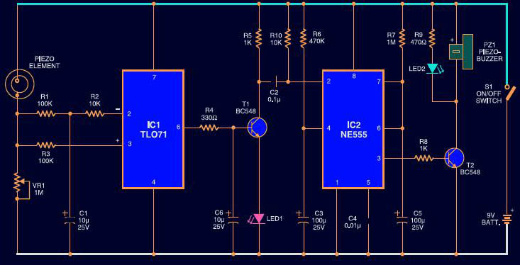
Animal or Human Vibration Security Sensor


This circuit simulates a seismic sensor to detect vibrations/ sounds. It is very sensitive and can detect vibrations caused by the movement of animals or human beings. So it can be used to monitor protected areas to restrict entry of unwanted persons or animals.
click to enlarge

  The circuit uses readily available components and the design is straightforward. A standard piezo sensor is used to detect vibrations/sounds due to pressure changes. The piezo element acts as a small capacitor having a capacitance of a few nanofarads. Like a capacitor, it can store charge when a potential is applied to its terminals. It discharges through VR1, when it is disturbed. In the circuit, IC TLO71 (IC1) is wired as a differential amplifier with both its inverting and non-inverting inputs tied to the negative rail through a resistive network comprising R1, R2 and R3. Under idle conditions (as adjusted by VR1), both the inputs receive almost equal voltages, which keeps the output low.
TLO71 is a low-noise JFET input op-amp with low input bias and offset current. The BIFET technology provides fast slew rates. Capacitor C1 is provided in the circuit to keep the differential input of IC1 for better performance. When the piezo element is disturbed (by even a slight movement), it discharges the stored charge.
 This alters the voltage level at the inputs of IC1 and the output momentarily swings high as indicated by green LED1. This high output is used to trigger switching transistor T1, which triggers monostable IC2. The timing period of IC2 is determined by R7 and C5. With the shown values, it will be  around two minutes. The high output from IC2 activates T2 and the buzzer starts beeping along with red light indication from LED2.
  Assemble the circuit on a common PCB and enclose in a suitable cabinet. Connect the piezo element to the PCB using single-core shielded wire. Enclose the piezo element inside a rustproof, small aluminium box. The piezo element should be firmly glued to the enclosure facing the fine side towards the case. Fix the sensor assembly on the back side of a ceramic tile or granite tile with good adhesive. Fix the tile (or bury it in the earth) near the entrance with the sensor assembly facing downwards. Whenever a pressure change develops near the sensor, the circuit will be activated.

security counter for Doors


This simple circuit produces a warning beep when somebody crosses a protected area in your home or office. The switch, hidden below the floor mat, triggers the alarm when the person walks over it. 
click to enlarge

 The circuit uses a conductive foam as the switch. It can be two small pieces of conductive pads usually used to pack sensitive ICs as antistatic cover. Alternatively, you can make the switch by coating conducting carbon ink on two small pieces of a copper-clad board. When the circuit is in standby mode, transistor T1 does not conduct, since its base is floating.
 When the person walks, the switch is pressed and current flows through R1 and the switch to provide positive bias to transistor T1. Transistor T1 conducts and its collector voltage drops, which acts as a negative trigger input for the monostable wired around IC NE555 (IC1). IC1 outputs a pulse of fifty-seconds duration with preset values of R4 and C3. This pulse is applied to the buzzer through transistor T2. The buzzer sounds a warning beep on unauthorised entry. The pulse duration can be changed to the desired value by changing the values of R4 and C 3 . Resistor R2 in the circuit makes the trigger pin of IC1 high to prevent false triggering.
 Assemble the circuit on a generalpurpose PCB and enclose in a plastic case. Use a 9V battery to power the circuit. Connect the touchpad switch with the PCB and hide under the mat at the entrance. The PCB can be mounted on the nearby wall. Make the switch carefully using conducting foam or copper clad coated with conducting ink. Place the two pieces with their conducting surface facing each other. Solder carefully a thin copper electric wire and ensure that it makes contact when the two plates touch together on pressing. Provide two 1cm rubber tabs between the plates to avoid touch in the standby mode.

Sunday, June 26, 2011

Security Officer


Here is a circuit that can be used in offices, stores, warehouses, etc during night to check whether the watchman of your establishment is on duty. For operation, it uses an existing telephone (e.g. in office or store) closest to the watchman’s post. The watchman is given an audio alert signal by just ringing the office/store telephone once (minimum) from your residence or any other place, preferably using your mobile phone. The ring is detected by the given circuit and the watchman is also given a visual alert signal by a glowing lamp. The lamp remains ‘on’ for a duration of nearly 60 seconds soon after the ringtone. 
click to enlarge

The watchman is given an instruction to register his presence by simply pointing his torch-light beam towards a wall-mounted LDR sensor unit (without lifting the handset off-cradle of the ringing telephone). This is to be done within the time period during which the alert lamp glows. If he fails to do it within the permissible time, the circuit registers his absence by incrementing a count. If he does, the count remains unaltered.
 Up to nine separate alert rings are considered here. The count displayed is the number of times the watchman failed to register his presence. The mobile phone records the called number and call time, and it can be used with the displayed count to get the timing details.
 The telephone lines (TIP and RING) in the circuit are connected across optocoupler MCT2E (IC1) through a resistor-capacitor (R1-C1) combination. The diode in the optocoupler conducts only during ring pulses. The collector of the optocoupler transistor is normally off and a 5V signal is available here. This signal is connected to the trigger input of IC 555 (IC2) configured in monostable mode. The time constant of IC2 is set to nearly one minute (1.1RxC). Its output pin 3 is low during normal mode of operation and the relay is de-energised.
 When the phone rings, the internal transistor of the optocoupler conducts to cause a high-to-low transition at trigger pin 2 of monostable IC2. Timer IC2 gets triggered on this trailing edge to energise relay RL1. This relay is used to switch on alert lamp L1. The circuit doesn’t respond to additional trigger inputs for the set duration of the monostable. The caller may cut the phone call after hearing ringback tone from the called phone. The sensor circuit formed using LDR1 activates another monostable 555 (IC6). LDR1 has a resistance of 2.2 kilo-ohms in daylight, which drops below 50 ohms when torchlight beam falls on it. (An LDR of nearly 2cm diameter has been used in this circuit.) Comparator LM358 (IC5) compares the level set at pin 3 (nearly 1V, set using a 10k pot) with the level at pin 2.
 When no light is falling on LDR1, its voltage is above 1V and IC5 has a low output at its pin 1. When light is falling on LDR1, its voltage drops below 1V and IC5 output at its pin 1 becomes high. This lowto- high transition is NANDed with the output of monostable IC2 (via inverters gates N1 and N2) to form the trigger signal for monostable IC6. So the trigger input is normally high, which falls when torchlight beam is focused on LDR1. It returns to high state when torchlight is switched off. So the torch is used as a remote for triggering monostable IC6 and this triggering is enabled only when alert lamp L1 is ‘on.’
 Monostable IC6 has a time constant of nearly one minute (1.1RxC). It is used to form a down clock signal for 4-bit up-/down-counter 74LS192 (IC7). Counter IC7 has two separate clocks for up and down counts (refer to the table). For correct counting, it needs one clock line to be high during high-tolow transition of the other clock line. Otherwise, it counts erratically.
 To operate counter IC7, the voltage levels and timings of the two clock inputs (up and down) are to be properly adjusted. Both trigger inputs, i.e. up and down clocks, are asynchronous. The output of monostable IC2 is filtered using capacitor C4 to remove unwanted transitions and inverted using Schmitt trigger inverter 74LS14 (IC3). This forms a signal with correct rising and falling edges. The inverted signal from pin 6 of gate N3 is used as the up clock.
 Counter 74LS192 (IC7) is reset to zero state by making its reset pin 14 high through reset switch S1. The 7-segment, commonanode display DIS1 is driven through IC 74LS47 (IC8). When the phone rings, count
‘1’ is displayed after nearly one minute. This happens if the watchman fails to focus the torchlight beam on LDR1. If LDR1 receives light from the torch of the watchman within the allowed time period, the down clock remains high until the up clock is high. The counter counts up and then down, so, in effect, the count remains unchanged. All components, except LDR1, are kept in a sealed cabinet with locking arrangement. Only LDR1 is wall-mounted and visible outside. This is done to avoid manual resetting of the counter. The circuit is to be powered by a battery to avoid resetting of the count during power failure. The working procedure can be summarised as follows:
 1. Initially, when the power supply isswitched on, power-on-reset components C8 and R13 reset
    counter IC7 and the display shows ‘0.’
2. Now dial the telephone number (where parallel system is installed) from outside or from your      
    mobile. For the first ring, relay RL1 energises and alert lamp L1 glows.
3.When alert lamp L1 is off, the counter is incremented by ‘1.’
4. If the watchman focuses the torchlight beam on LDR1 within the glowing time of alert lamp    
   L1, the counter first counts up and then counts down and finally the display shows 0. This   
   indicates that the watchman is present.
5. If the watchman focuses the torchlight beam on LDR1 after alert lamp L1 goes off, upcounting   
   takes place and the display shows ‘1.’ This indicates that the watchman is absent.

Safety Guard For Home Appliance


Protect your home appliances from voltage spikes with this simple time delay circuit. At the heart of the circuit is IC CD4060, which consists of two inverter gates for clock generation and a 14-bit binary ripple counter. 
click t enlarge

Here the clock oscillations are governed by resistor R1 and capacitor C1. In this circuit, only two outputs of the IC (Q5 and Q14) have been used. Q5 is connected to an LED (LED1) and Q14 is used to trigger the gate of the SCR through D4 as well as reset the counter. The anode of the SCR is connected to +9V and the cathode is connected to the relay coil. The other pin of the relay coil is connected to the negative supply, while its contacts are used for switching on the appliances.
Whenever power to the appliances is switched on or resumes after mains failure, the oscillator starts oscillating and LED1 blinks. This continues for three minutes. After that, Q14 output of IC CD4060 goes high to trigger the gate of the SCR through D4. At this moment, the voltage is available at the cathode of the SCR, which energises the relay coil to activate the appliance and LED2 glows. Switch S1 is used for quick start without waiting for delay.

Laser Controlled Door Opener


This automatic door opener can be made using readily available components. The ectromagnetic relay at the output of this gadget can be used to control the DC/AC door-opener motor/solenoid of an electromechanical door opener assembly, with slight intervention in its electrical wiring.
click to enlarge

  A laser diode (LED1) is used here as the light transmitter. Alternatively, you can use any available laser pointer. The combination of resistor R1 and diode D1 protects the laser diode from over-current flow. By varying muliturn trimpot VR1, you can adjust the sensitivity. (Note that ambient light reflections may slightly degrade the performance of this unit.)
  Initially, when the laser beam is falling on photo-transistor T1, it conducts to reverse-bias transistor T3 and the input to the first gate (N1) of IC1 (CD4001) is low. The high output at pin 3 of gate N1 forward biases the LED-driver transistor (T4) and the green standby LED (LED2) lights up continuously. The rest of the circuit remains in standby state.
 When someone interrupts the laser beam, photo-transistor T1 stops conducting and transistor T3 becomes forward-biased. This makes the output of gate N1 go low. Thus LED-driver transistor T4 becomes reverse-biased and LED2 stops glowing. At the same time, the low output of gate N1 makes the output of N2 high. Instantly, this high level at pin 4 of gate N2 triggers the monostable multivibrator built around the remaining two gates of IC1 (N3 and N4). Values of resistor R8 and capacitor C1 determine the time period of the monostable.
 The second monostable built around IC2 (CD4538) is enabled by the high-going pulse at its input pin 12 through the output of gate N4 of the first monostable when the laser beam is interrupted. As a result, relay RL1 energises and the door-opener motor starts operating. LED3 glows to indicate that the door-opener motor is getting the supply. At the same time, piezobuzzer PZ1 sounds an alert. Transistor T5, whose base is connected to Q output (pin 10) of IC2, is used for driving the relay. Transistor T6, whose base is connected to Q output of IC2, is used for driving the intermittent piezobuzzer. ‘On’ time of relay RL1 can be adjusted by varying trimpot VR2. Resistor R9, variable resistor VR2 and capacitor C3 decide the time period of the second monostable and through it on time of RL1. The circuit works off 12V DC power supply.   
 Assemble it on a general- purpose PCB. After construction, mount the laser diode and the phototransistor on opposite sides of the doorframe and align them such that the light beam from the laser diode falls on the phototransistor directly. The motor connected to the pole of relay contacts is the one used in electromechanical door-opener assembly. If you want to use a DC motor, replace mains AC connection with a DC power supply.

Universal Security System


This reliable and easy-to-operate electronic security system can be used in banks, factories, commercial establishments, houses, etc.
The system comprises a monitoring system and several sensing zones. Each sensing zone is provided with a closed-loop switch known as sense switch. Sense switches are fixed on the doors of premises under security and connected to the monitoring system. As long as the doors are closed, sense switches are also closed. The monitoring system can be installed at a convenient central place for easy operation. 
click to enlarge

 Fig. 1 shows the monitoring circuit only for zone 1 along with the common alarm circuit. For other zones, the monitoring circuit is identical, with only the prefixes of components changing as per zone number. Encircled points A, B, and C of each zone monitoring circuit need to be joined to the corresponding points of the alarm circuit (upper half of Fig. 1).
When zone 1 sensing switch S11, zone on/off slide switch S12, and system on/off switch S1 are all on, pnp transistor T12 reverse biases to go in cut-off condition, with its collector at around 0 volt. When the door fitted with sensor switch S11 is opened, transistor T12 gets forward biased
and it conducts. Its collector voltage goes high, which forward biases transistor T10 via resistor R10 to turn it on. (Capacitor C10 serves as a filter capacitor.) As a result, the collector voltage of transistor T10 falls to forward bias transistor T11, which conducts and its collector voltage is sustained at a high level. Under this latched condition, sensor switch S11 and the state of transistor T12 have no effect. In this state, red LED11 of the zone remains lit.
 Simultaneously, the high-level voltage from the collector of transistor T11 via diode D10 is applied to VDD pin 5 of siren sound generator IC1 (UM3561) whose pin 2 is grounded. Resistor R3 connected across pins 7 and 8 of IC1 determines the frequency of the in-built oscillator. As a result, IC1 starts generating the audio signal output at pin 3. The output voltage from IC1 is further amplified by Darlington pair of transistors T1 and T2. The amplified output of the Darlington pair drives the loudspeaker whose output volume can be controlled by potentiometer VR1. Capacitor C1 serves as a filter capacitor.
 The circuit continues to sound the alarm until zone door is closed (to close switch S11) and the reset switch is pressed momentarily (which causes transistor T10 to cut off, returning the circuit to its initial state).
 The system operates off a 3V DC battery or recharging battery with charging circuit or battery eliminator. If desired, more operating zones can be added. Initially keep the monitoring system switch S1 off. Keep all the zone doors fixed with sensing switches S11, S21, S31, S41, etc closed. This keeps the sensing switches for respective zones in closed position. Also keep zone slide switches S12, S22, S32, S42, etc in ‘on’ position. This puts the system in operation, guarding all the zone doors.
  Now, if the door of a particular zoneis opened, the monitoring system sounds an audible alarm and the LED corresponding to the zone glows to indicate that the door of the zone is open. The alarm and the LED indication will continue even after that particular door with the sensing switch is immediately closed, or even if that switch is removed/damaged or connecting wire is cut open.
  Any particular zone in the monitoring system can be put to operation or out of operation by switching on or switching off the corresponding slide switch in the monitoring system.

Sunday, June 19, 2011

Simple Low-Cost Digital Code Lock


Many digital code lock circuits have been published in this magazine. In those circuits a set of switches (conforming to code) are pressed one by one within the specified time to open the lock. In some other circuits, custom-built ICs are used and positive and negative logic pulses are keyed in sequence as per the code by two switches to open the lock. 
click to enlarge

  A low-cost digital code lock circuit is presented in this article. Here the keying-in code is rather unique. Six switches are to be pressed to open the lock, but only two switches at a time. Thus a total of three sets of switches have to be pressed in a particular sequence. (Of these three sets, one set is repeated.) The salient features of this circuit are:
1. Use of 16 switches, which suggests that there is a microprocessor inside.
2. Elimination of power amplifier transistor to energise the relay.
3. Low cost and small PCB size.
  An essential property of this electronic code lock is that it works in monostable mode, i.e. once triggered,the output becomes high and remains so for a period of time, governed by the timing components, before returing tothe quiescent low state. In this circuit, timer IC 555 with 8 pins is used. The IC is inexpensive and easily available. Its pin 2 is the triggering input pin which, when held below 1/3 of the supply voltage, drives the output to high state. The threshold pin 6, when held higher than 2/3 of the supply voltage, drives the output to low state. By applying a low-going pulse to the reset pin 4, the output at pin 3 can be brought to the quiescent low level. Thus the reset pin 4 should be held high for normal operation of the IC.
  Three sets of switches SA-SC, S1- S8 and S3-S4 are pressed, in that order, to open the lock. On pressing the switches SA and SC simultaneously, capacitor C3 charges through the potential divider comprising resistors R3 and R4, and on releasing these two switches, capacitor C3 starts discharging through resistor R4. Capacitor C3 and resistor R4 are so selected that it takes about five seconds to fully discharge C3.
 Depressing switches S1 and S8 in unison, within five seconds of releasing the switches SA and SC, pulls pin 2 to ground and IC 555 is triggered. The capacitor C1 starts charging through resistor R1. As a result, the output (pin 3) goes high for five seconds (i.e. the charging time T of the capacitor C1 to the threshold voltage, which is calculated by the relation T=1.1 R1 x C1 seconds).
  Within these five seconds, switches SA and SC are to be pressed momentarily once again, followed by the depression of last code-switch pair S3-S4. These switches connect the relay to output pin 3 and the relay is energised. The contacts of the relay close and the solenoid pulls in the latch (forming part of a lock) and the lock opens. The remaining switches are connected between reset pin 4 and ground. If any one of these switches is pressed, the IC is reset and the output goes to its quiescent low state. Possibilities of pressing these reset switches are more when a code breaker tries to open the lock.
 LED D5 indicates the presence of power supply while resistor R5 is a current limiting resistor. The given circuit can be recoded easily by rearranging connections to the switches as desired by the user.

Security System Switcher


An audio signal can be used as a form of input to control any security system. For example, an automatic security camera can be configured to respond to a knock on the door. The circuit described here allows the security system to automatically switch on when a master switch is in on state. It uses a transducer to detect intruders and a 5V regulated DC power supply provides power to the circuit.

click to enlarge

  As shown in Fig.1,a condenser microphone is connected to the input of small signal preamplifier built around transistor T1. Biasing resistor R1 determines to a large extent the microphone sensitivity. A microphone usually has an internal FET which requires a bias voltage to operate. The sound picked up by the microphone is amplified and fed to input pin 2 of IC1 (LMC555) wired in monostable configuration.
 IC2 (CD4538B) is a dual, precision monostable multivibrator with independent trigger and reset controls. The output of IC1 is connected to the first trigger input pin 4 of IC2(A) through switch S1. If an intruder opens or breaks the door, IC1 is triggered by sound signals; the timer output pin 3 of IC1 goes high and enables first monostable multi vibrator IC2(A). IC2(A) provides a time period of around 5 to 125 seconds, which is adjusted with preset VR1.
 Another monostable multivibrator IC2(B) also provides a time period of around 25 to 600 seconds, which is adjusted with preset VR2. The output of IC2(B) is used to energise relay RL1. Indicator LED1 is provided to display the relay activity. Any AC/DC operated security gadget is activated or deactivated through a security switch. Thus, the security switch of the gadget is connected in the n/o contacts of the relay. you can also operate highpower beacons, sirens or hooters in place of the security switch for any AC/DC operated security gadget.
Assemble the circuit on a general- purpose PCB and enclose it in a cabinet as shown in Fig. 2 along with 5V adaptor for powering the circuit. Connect the security switch according to the circuit diagram and use appropriate AC/DC power supply required to operate the security gadget.
 Warning! All relevant electrical safety precautions should be taken when connecting mains power supply to the relay contacts. With the help of single pole double throw (SPDT) switch S1, internal or external trigger input (active high signal) can be selected.

Electronic cardlock system


The circuit presented here can be used as a lock for important electronic/electrical appliances. When card is inserted inside its mechanism, depending upon the position of punched hole on the card, a particular appliance would be switched on.

click to enlarge

  The card is inserted just like a floppy disk inside the disk drive. This card should be rectangular in shape with only one punched hole on it.
  The circuit uses eight photo-transistors (T1 through T8). When there is no card in the lock, light from incandescent lamp L1 (40-watt, 230V) falls on all the photo- transistor detectors. Transistor T8 is used as enable detector for IC1 (74LS244). When light is incident on it, it conducts and its collector voltage goes low. This makes transistor T16 to cut-off, and its collector voltage goes high. This logic high on its collector terminal will inhibit IC1 as long as light is present on phototransistor T8. IC1 will get enabled only when the card is completely inserted inside the lock mechanism. This arrangement ensures that only the selected appliance is switched on and prevents false operation of the system.
 You can make these cards using a black, opaque plastic sheet. A small rectangular notch is made on this card to indicate proper direction for insertion of the card. If an attempt is made to insert the card wrongly, it will not go completely inside the mechanism and the system will not be enabled.
 When card for any appliance (say appliance 1) is completely inserted in the mechanism, the light will fall only on photo-transistor T1. So only T1 will be on and other photo-transistors will be in off state. When transistor T1 is on, its collector voltage falls, making transistor T9 to cut-off. As a result, collector voltage of transistor T9 as also pin 2 of IC1 go logic high. This causes pin 18 (output Q1) also to go high, switching LED1 on. Simultaneously, output Q1 is connected to pin 1 of IC2 (ULN2003) for driving the relay corresponding to appliance  1. Similarly, if card for appliance 2 is inserted, only output pin 16 (Q2) of IC1 will go highmaking LED2 on while at the same time energising relay for appliance 2 via ULN2003. The same is true for other cases/appliances also.
 The time during which card is present inside the mechanism, the system generates musical tone. This is achieved with the help of diodes D1 through D7 which provide a wired-OR connection at their common-cathode junction. When any of the outputs of IC1 is logic high, the commoncathode junction of diodes D1 through D7 also goes logic high, enabling IC3 (UM66) to generate a musical tone.
  In this circuit IC1 (74LS244) is used as buffer with Schmitt trigger. All outputs (Q1 through Q7) of this IC are connected to IC2 (ULN2003) which is used as relay driver. IC2 consists of seven highcurrent relay drivers having integral diodes. External free-wheeling diodes are therefore not required.
 When an input of this IC is made logic high, the corresponding output will go logic low and relay connected to that pin gets energised. This switches on a specific appliance and the corresponding LED.
 Once a specific card is inserted to switch on a specific relay, that relay gets latched through its second pair of contacts. Thus even when the card is removed, the specific appliance remains on. The same holds true for all other relays/ appliances as well. The only way to deenergise a latched relay after removal of the corresponding card is to switch off the corresponding switch (S1 through S7) which would cut-off the supply to the desired relay.
  The +5V and +12V supplies can be obtained with conventional arrangement using a step-down transformer followed by rectifier, filter and regulator (using 7805 and 7812 etc).

Tuesday, June 14, 2011

Radio Frequency Based Attendance Register

Traditionally the attendance at an establishment is usually done in a book register. It is time consuming. It is very difficult to verify the attendance over long periods. This method is very time consuming and very difficult to verify the attendance over a week or above. Keeping attendance registers is space consuming. Here chances of doing malpractice in marking attendance are high.
 RFID based attendance system uses RFID tags for each person. A person marks the attendance by swiping the tag near RFID reader module. The attendance is temporarily saved in the EEPROM. At any time the circuit can be connected to a computer and the attendance is moved from EEPROM to a text file in computer. It has following advantages. (1) Simplicity and reliability, (2) Saving attendance in a computer allows easy verification and longer record keeping.
It works on radio frequency transmitters and receivers. Each person is given a RF ID card which is having a unique code. When it is swiped on a RF ID card reader, it reads the code and is stored. The attendance is temporarily saved in the EEPROM. At any time the circuit can be connected to a computer and the attendance is moved from EEPROM to a text file in computer. The advantage of this system is simplicity and reliability. Saving attendance in a computer allows easy verification and longer record keeping.
The DT125R series RFID Proximity OEM Reader Module has a built-in antenna in minimized form factor. It is designed to work on the industry standard carrier frequency of 125 kHz. This LF reader module with an internal or an external antenna facilitates communication with Read-Only transponders type UNIQUE or TK5530 via the air interface. The tag data is sent to the host systems via the wired communication interface with a protocol selected from the module pinout. The LF DT125R module is best suited for applications in Access Control, Time and Attendance, Asset Management, Handheld Readers, Immobilizers, and other RFID enabled applications.The AUTOMATIC DATA COLLECTION Technology used in th RFID reader.
WORKING

 Microcontroller reads time from real time chip DS12887. Whenever a RFID tag is brought near RFID module, it sends the card number in ASCII fomat to the microcontroller.  The microcontroller compares this number with those numbers in the  EEPROM. If match is found, it first check whether it is a master card, then it displays menu for master card. If not, it displays the ID number and then sends the time and date details along with ID number to EEPROM for marking daily attendance. If no matches found, the microcontroller displays ‘Card Not Programmed’ in LCD.

            Master card menu consists of set time, add, edit, delete, transfer. The various options are selected using the keypad keys- up, down, enter, cancel. Keypad encoder converts the key pressed into corresponding hex file. The output from RFID is given as the serial  input. The card ID number is 8 bytes long and two extra bytes serve as start and stop bits.

Set time: It is used to edit the time of RTC. The time is entered using the keypad.

Add: It is used to add a new tag and store the new tag number and ID number to EEPROM.

Edit: It is used to edit the card ID number. The new ID number is entered through keypad.

Delete: It is used to delete a card from record.

Transfer: This option is used to transfer the marked attendance stored in EEPROM to the computer.

MAX232 is used to convert the TTL voltage to RS232 compatible voltage. Real time clock is used to provide the date, month, and year details for marking the attendance.
Almost all electronic devices used in electronic circuits need a dc source of power supply to operate .The source of dc power is used to establish the dc operating points for the passive and active electronic devices incorporated in the system. The combination of a transformer, a rectifier, and a filter constitutes an ordinary dc supply, also called an unregulated power supply. For many applications in electronics unregulated power supply is not good because of the following reasons.
·                    Poor regulation.
·                    Variations in the ac supply main.
·                    Variations in temperature.

Download full Report with Source code

Twitter Delicious Facebook Digg Stumbleupon Favorites More