Showing posts with label TRANSISTER BASED PROJECTS. Show all posts

Wednesday, July 6, 2011

Rain Detector Using Transistor


  This rain detector will give you a heads-up the instant it starts to rain, hopefully giving you time to close windows and bring in possessions. 
click on this image to enlarge

The battery-powered circuit draws virtually no current when the sensor is dry and the current consumption is low when the buzzer is activated so a couple of AA cells will last a long time. Alternately, a molded power supply with a simple voltage regulator to drop the voltage to 3 volts could be used. 
The circuit is basically a handy flasher circuit that operates well on only 3 volts using ordinary silicon transistors. When the circuit is triggered, the buzzer is pulsed about once per second for a very short time, giving it a "dripping water" sound which seems appropriate. A slower, longer beep may be had by increasing the 1 uF capacitor. The 10 k resistor may be increased for a longer beep time without decreasing the beep rate but at some point the circuit will cease to function properly, depending on the gain of the transistors. 


Monday, June 27, 2011

Low-Cost Transistorised Inverter


This is an inexpensive fully transistorised inverter capable of driving medium loads of the order of 40 to 60 watts using battery of 12V, 15 Ah or higher capacity. Transistors T1 and T2 (BC548) form a 50Hz multivibrator.
click on image to enlarge

For obtaining correct frequency, the values of resistors R3 and R4 may have to be changed after testing. The complementary outputs from collectors of transistors T1 and T2 are given to PNP darlington driver stages formed by transistor pairs T3-T4 and T6-T7 (utilising transistors BD140 and 2N6107). The outputs from the drivers are fed to transistors T5 and T8 (2N3055) connected for push-pull operation.

Somewhat higher wattage can be achieved by increasing the drive to 2N3055 transistors (by lowering the value of resistors R7 and R8 while increasing their wattage). Suitable heatsinks may be used for the output stage transistors. Transformer X1 is a 230V primary to 9V-0-9V, 10A secondary used in reverse.

Universal IR Remote Control


Here is a circuit which can switch on and switch off any appliance with the help of a common type of infra-red remote control (transmitter). 
click to enlarge

This circuit senses the IR pulse and then controls the appliance accordingly. The circuit functions such that a short pulse from the remote tran- smitter switches on the triac (and the load) while a longer pulse switches off the triac as also the load. The circuit is built around hex inverter IC CD 4049. When the infra-red pulse is received by the sensor, its output (Note: Here VR1 denotes the in-circuit resistance of preset VR1.) The output of multivibrator is fed to the base of current amplifier 2N3055 via resistor R2 (1kilo-ohm). The brakelight bulb is connected in series with the collector of 2N3055. The flashing rate of this bulb is adjusted by 100k preset (VR1). 
Transistor 2N3055 may get heated due to high current switching action; hence a small heatsink, similar to the type used in television power supply, is recommended. The category of 2-wheelers which do not have a battery, can use the bridge rectifier circuit shown here. Several designs of round, square and rectangular reflectors are available which may be used in conjunction with any suitable 12V bulb with proper rating (around 20 watts). However, if flashing of the brake- light affects intensity of headlight bulb, reduce the rating of brakelight bulb to 10 watts.

security Alarm circuit


As you can clearly see from the schematics, the circuit is utterly primitive and consists of two identical transistor switches. Each has its own alarm LED and they're coupled to a neat 82dB buzzer.
click to enlarge

The two 1N4148 diodes are used to prevent a signal from one sensor from triggering both LEDs. The sensors used are either wire loops or normally closed reed switches or even a combination of both. You could, for example, tie a wire loop to your suitcase and place a reed switch to the door of your hotel room.
Since this little alarm is intended to be kept in arms reach at all times, there aren't any provisions for automatic shutdown after a certain period of time. The buzzer will sound until you turn the whole circuit off or connect the wire loop back to the jumpers. The same goes for the two LEDs, each indicating its own zone.
Construction is not critical and there aren't any traps for the novice. The two 100n capacitors aren't really necessary, I just included them to make sure that there is no noise interference coming from the long wire loops. For transistors, you can use any NPN general-purpose audio amplifiers/switches (BC 107/108/109, BC 237/238, 2N2222, 2N3904...). Assemble the circuit on perf board. Together with the buzzer and a 9V battery, it should easily fit in a pocket-sized plastic box smaller than a pack of cigarettes. A fresh battery should suffice for weeks of continuous operation.

Object Counter Circuit


Presented here is the cheapest 8-digit programmable object or event counter. It is a fail-proof, fool-proof, power failure-proof, one evening project. A general-purpose (arithmetic) calculator has some inherent shortcomings which can, however, be used in many ways by proper programming sequences.
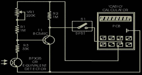
click to enlarge

For example, there is no squaring key in a general-purpose calculator, but it can not only square it has even the inherent capability of a single touch successive multiplication, thus giving us a choice of making a geometric progression (G.P.) or successive addition or forming an arithmetic progression (A.P.). For example, operating the keys 5,x,=,=,... you obtain the G.P. 5,25,125,625,... or by operating keys 5,x,4,=,=,=,..., you get the G.P.: 4,20, 100,500,... Next, operate keys: 5,+, 2,=,=,... to get the A.P.: 5,7,9,11,13,... The latter facility (A.P.) has been used here to count the objects by programming the calculator keys 1,+,=,=,... When you open the calculator (such as ‘Casio’), you will find that the conductive silicon key pads bridge the two terminals of a key, when depressed. Locate the switch terminals for (=) key and check the polarity of the terminals with respect to the battery negative. The terminal which is found to be positive is to be connected to the junction of R2 and VR1, and the other terminal is to be connected to switch S1 as shown in the figure. The negative battery terminal is to be connected to emitters of photo-transistor and transistor T1. (There may be slight difference in the use of key terminals in different brands of calculators.) The optical sensor used here is BPX25, a very sensitive photo-transistor which has a built-in lens to focus the incident light on to the chip. Only two leads, emitter and collector, have been used. When light falls on the sensor, it conducts as if it had got forward biased. A variable resistor of 220k in series with another fixed resistor of 1 M (selected by trial) has been used at the base of transistor T1 (BC149C/BC 549C) to set the threshold level for its conduction, depending upon the intensity of light used. When light is obstructed, BPX goes to cut-off, transistor T1 conducts and the terminal of (=) key which is connected via switch S1 (assuming closed), goes low. This is equivalent to depression of the (=) key. When light again falls on the sensor, it conducts and the base of transistor T1 goes low, throwing it to cut-off, so that its collector and hence the (=) key gets connected to the positive bus via 1 M resistor R2. A pulse is passed on and the calculator advances by 1. Current drain from the battery is less than 50 µA, which a button cell can easily provide. The counter is slow but there is no switch debouncing effect present, which makes the counter highly reliable and ideal as a slow event counter in applications such as visitor counter. Further, the circuit is auto-locked, since any resetting is possible only when BPX is in the cut-off position, i.e., in darkness. To program, cover the phototran- sistor and operate keys : 1,+,=. In case of a deadlock in programming, miniature switch S1 may be used to enable isolation of the (=) key. Set the 220k preset according to the ambient and the incident light, so that the calculator counts when light is cut-off and again allowed to fall when obstruction is removed. If it is used to count visitors in a well day-lighted environment, only a white washed wall or a white paper pasted on the opposite door panel is sufficient. For indoor applications, a specific source of light is required. Both the source of light as well as the BPX should then be mounted in opaque (preferably black) tubes and a lens be fitted in the light-source tube to focus the light on to the photo-transistor. BC149C/549C is preferred due to its large current gain of the order of 300 at 10 µA, compared to 150 that of BC548B, so that the instrument becomes more sensitive.

LEDs Display


The circuit presented here uses bicolour LEDs to generate a display in three colours, namely, red,green, and yellowish green. Transistors T1 through T20 form a grid to which common-cathode bicolour LEDs (LED1 through LED10) are connected. 
click to enlarge

 Transistors T1 through T10 have their collector terminals connected to the emitter of transistor T21. Similarly, transistors T11 through T20 have their collector terminals connected to the emitter of transistor T22. The bases of each pair of transistors (i.e.  T1 and T11, T2 and T12,…, T10 and T20) are tied to outputs Q0, Q1,…, Q9, respectively, of IC1 (CD4017) through 10-kiloohm resistors as shown in the figure. Positive supply to collectors of transistors T1 through T10 is controlled by transistor T21. Similarly, positive supply to collectors of  transistors T11 through T20 is controlled by transistor T22.
IC1 and IC2 are decade counters. Clock pulse to IC1 is provided by the oscillator circuit comprising NOR gates N1 and N2. The outputs of IC1 advance sequentially  with each clock. (Any other source of squarewave pulses also serves the purpose.)IC2 is used to select the mode of display. Clock input pin 14 of IC2 is connected to Q9 output of IC1. Thus IC2 receives one pulse after every ten pulses received by IC1.
  When the circuit is switched on, Q0 output of IC2 is active high. Thus transistor T21 gets forward biased via diode D3 and it conducts to extend positive supply to transistors T1 through T10. Transistors T1 through T10 are forward biased sequentially by Q0 through Q9 outputs of IC1, i.e. at a time only one of these ten transistors is forward biased (on). Thus only red LED parts of bicolour LEDs light up sequentially.  Transistor T22 is not conducting at this moment.) When red LED part of LED10 glows, IC2 receives a clock pulse and its Q1 output goes high. Transistor T21 still conducts, as it is forward biased through diode D6, and next again via diode D5. Thus red LEDs complete two more glowing sequences.
 After completion of the third glowing sequence of red LEDs, when Q3 output of IC2 goes high, transistor T21 stops conducting and T22 starts conducting with the next three sequences of green LEDs of bicolour LEDs (LED1 through LED10) glowing sequentially. After completion of three sequences of green LEDs, output Q6 of IC2 goes high.
Now both transistors T21 and T22 conduct due to diodes D1 and D2. Thus both red and green LEDs in bicolour LEDs (LED1 through LED10) glow sequentially. The effect of red and green LEDs glowing together is a distinct yellowish orange colour. This sequence repeats four times.
Thereafter, the whole sequence repeats, starting with red LEDs. Thus the bicolour LED display shows three colours—red, green, and yellowish green—one after the other. The speed of display can be controlled by preset VR1. One can omit automatic selection of different colours by omitting IC2 and replacing connections to pins 3, 5, and 7 of IC2 with SPDT switches. (Thus diodes D3-D12 are also omitted.)

IR Headphone


Using this low-cost project one can reproduce audio from TV without disturbing others. It does not use any wire connection between TV and headphones. In place of a pair of wires, it uses invisible infrared light to transmit audio signals from TV to headphones. Without using any lens, a range of up to 6 metres is possible. Range can be extended by using lenses and reflectors with IR sensors comprising transmitters and receivers.
click to enlarge

 IR transmitter uses two-stage transistor amplifier to drive two series-connected IR LEDs. An audio output transformer is used (in reverse) to couple audio output from TV to the IR  transmitter. Transistors T1 and T2 amplify the audio signals received from TV through the audio transformer. Lowimpedance output windings (lower gauge or thicker wires) are used for connection to TV side while high-impedance windings are connected to IR transmitter.  
This IR transmitter can be powered from a 9-volt mains adapter or battery. Red LED1 in transmitter circuit functions as a zener diode (0.65V) as well as supply-on indicator. IR receiver uses 3-stage transistor amplifier. The first two transistors (T4 and T5) form audio signal amplifier while the third transistor T6 is used to drive a headphone. Adjust potmeter VR2 for max. clarity.

Direct photo-transistor towards IR LEDs of transmitter for max. range. A 9-volt battery can be used with receiver for portable operation.

Teleconferencing System


Here is a low-cost teleconferencing system that lets you talk to two persons at a time in any part of the world over two telephone lines. The circuit makes use of a coupling transformer and some passive components. 
click to enlarge

 The circuit is connected between the two telephone lines. It works like this: When ‘X’ calls ‘A’ on the first telephone line, ‘A’ puts this call on hold, dials ‘Y’ on the other telephone line (which is free) and keeps this call too on hold, and slides switches S1 and S2 to ‘on’ position. Now ‘X,’ ‘A’ and ‘Y’ can talk to one another simultaneously over the two telephone lines.
 Both the primary and secondary coils of the coupling transformer consist of 500 turns of 40SWG insulated copper wire. At the secondary side, a small circuit is used for DC holding. This circuit is built around transistor T1 (BC547), resistors R2 and R3 (15 kiloohms and 100 ohms, respectively), condenser C3 (22μF, 63V) and two LEDs as indicators for both the primary and secondary sides. It provides proper DC characteristic to hold second telephone line in operation even though no telephone on that line is present.
  Here, transistor T1 acts like a resistor to DC and as high impedance for audio signals. The high impedance of the circuit is provided by condenser C3, which prevents any audio signal from appearing at the base of T1. Thus any audio voltage appearing across telephone line No. 2 will not cause a corresponding current in the transistor.

Sunday, June 26, 2011

High Watts Amplifier


The main changes made in this design was the addition of a clipping detector circuit and bias circuit modifications for the use of International Rectifier HEXFET MOSFET’s. Later modifications where made to the error amp and VAS stages which improved the overall sound of the amplifier. The power supply components for this amplifier are as follows and are expressed for Two Channels. 1 x Toroidal Transformer with a Core rating of 625VA. Primary windings are made to suit your local mains supply. Eg: for Australia One single primary winding with a 240VAC rating. For USA, 110VAC, 115VAC and I believe there is a 220-Volt AC mains supply in some areas of the United States. For the UK it would be 220 VAC to 240 VAC.
click to enlarge

The secondary windings are as follows.
2 x 50 volts AC at full load.
One 400 Volt 35 Ampere, bridge rectifier.
2 x 4.7K 5 Watt ceramic resistors
Minimum filter capacitor requirements would be 2 x 10,000uf 100 volt electrolytic.
Ideal capacity would be 40,000uf per voltage rail.
A suggested power supply schematic is shown below with the schematic of
The amplifier.
When using this type of MOSFET in the AV800 amplifier is strongly recommended that the output stage devices be matched. As it has been found that if this is not done then there is no guarantee that they will share the current under load. The Source resistors provide only a bit of local feedback and don’t in any way force the devices to current share. The best method I have found to work very well utilises just a 150 Ohm 1 watt resistor and a +15 volt DC power supply. If you look at the schematic below it shows how to connect and measure the N-channel devices and the P-channel devices. With the devices connected, as shown measure across R1 with a multimeter set to DC volts and measurement of between 3.8 volts and 4.2 volts will be shown. Simply match the device in-groups to a tolerance of +-100mv. Please note that you only have to match the n-channel to the n-channel devices and the pchannel to the p-channel devices, not the N-channel devices to the P-channel devices.


Sunday, June 19, 2011

Sensitive Temprature Switch


This temperature switch has a high sensitivity and is quite reliable. Here, in place of a single transistor, a Darlington pair has been used for switching. 
click to enlarge

  At normal room temperature germinum diode D1 (0A79 or equivalent) has a back resistance value of about 10 kiloohms.As a result Darlington pair, comprising transistors T1 and T2. Conducts and keeps the anode terminal of diode D2 at ground potential. Consequently, transistor T3 does not get base bias and thus relay RL1 is not activated.
 But when temperature increases. The back resistance of diode D1 decreases sharply, which results in cutting off of Darlington pair and forward biasing of transistor T3 via resistor R2 and diode D2. As a result, relay RL1 energises and switches on the alarm. Potmeter VR1 may be adjusted for required sensitivity.
  This simple circuit can be used as an overheat indicator, fire alarm, or it can be used in a constant temperature circuit for switching on a fan etc. The circuit can be easily assembled on a piece of veroboard. Diode sensor D1 must be of germanium type and not silicon.

LIGHT HOUSE


This project was designed for a model lighthouse  to flash a lamp in a simple sequence: two flashes of 2s with a short gap of 1s, followed by a longer gap of 5s before repeating the sequence.

CLICK TO ENLARGE

 The 555 timer is connected as an astable to provide clock pulses for the 4017 counter. The 4017 has ten outputs (Q0 to Q9) and each one becomes high (‘on’) in turn as the clock pulses are received. Outputs Q0, Q1, Q3 and Q4 are combined with diodes to produce the flash sequence. A transistor amplifies the current to power the lamp, or LED if you prefer (a 470W LED resistor is included on the stripboard layout). The 1MW preset controls the time period (T) of the 555 astable from about 0.1 to 1.5s, for example set T = 1s. For a different flash sequence connect the diodes to combine different 4017 outputs (Q0-Q9). If the full count from 0 to 9 is not required one of outputs can be connected to the reset input (pin 15). For example connecting Q8 (pin 9) to reset (pin 15) reduces the long gap at the end of the sequence to 3s (with T=1s).
Parts Required
• resistors: 470, 2k2, 22k, 100k • 555 timer IC, such as NE555
• capacitors: 0.1μF, 1μF 16V radial • 4017 counter IC
• diodes: 1N4148 × 4 • DIL sockets for ICs: 8-pin, 16-pin
• transistor: BC108 (or equivalent) • on/off switch
• 1M preset, horizontal • battery clip
• 6V 60mA MES lamp • 9V battery box for 6 × AA cells
• MES lampholder • stripboard: 19 rows × 21 holes

Twitter Delicious Facebook Digg Stumbleupon Favorites More