Showing posts with label Switching Circuits. Show all posts

Wednesday, June 29, 2011

Voice Switching Circuit

This circuit uses an MC2830 to form a voice activated switch ( VOX ). 
click on image to enlarge

A traditional VOX circuit is unable to distinguish between voice and noise in the incoming signal. In a noisy environment, the switch is often triggered by noise, or the activation sensitivity must be turned down. This circuit overcomes this weakness. The switch is activated by voice level above the noise and not activated by background noise. This is done by utilizing the differences in voice and noise waveforms. Voice waveforms generally have a wide range of variation in amplitude, whereas noise waveforms are more stable. The sensitivity of the voice activation depends on the value of R6. The voice activation sensitivity is reduced from 3.0dB to 8.0dB above the noise if R6 changes from 14k to 7.0k .

Monday, June 27, 2011

security Alarm circuit


As you can clearly see from the schematics, the circuit is utterly primitive and consists of two identical transistor switches. Each has its own alarm LED and they're coupled to a neat 82dB buzzer.
click to enlarge

The two 1N4148 diodes are used to prevent a signal from one sensor from triggering both LEDs. The sensors used are either wire loops or normally closed reed switches or even a combination of both. You could, for example, tie a wire loop to your suitcase and place a reed switch to the door of your hotel room.
Since this little alarm is intended to be kept in arms reach at all times, there aren't any provisions for automatic shutdown after a certain period of time. The buzzer will sound until you turn the whole circuit off or connect the wire loop back to the jumpers. The same goes for the two LEDs, each indicating its own zone.
Construction is not critical and there aren't any traps for the novice. The two 100n capacitors aren't really necessary, I just included them to make sure that there is no noise interference coming from the long wire loops. For transistors, you can use any NPN general-purpose audio amplifiers/switches (BC 107/108/109, BC 237/238, 2N2222, 2N3904...). Assemble the circuit on perf board. Together with the buzzer and a 9V battery, it should easily fit in a pocket-sized plastic box smaller than a pack of cigarettes. A fresh battery should suffice for weeks of continuous operation.

Object Counter Circuit


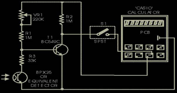
Presented here is the cheapest 8-digit programmable object or event counter. It is a fail-proof, fool-proof, power failure-proof, one evening project. A general-purpose (arithmetic) calculator has some inherent shortcomings which can, however, be used in many ways by proper programming sequences.
click to enlarge

For example, there is no squaring key in a general-purpose calculator, but it can not only square it has even the inherent capability of a single touch successive multiplication, thus giving us a choice of making a geometric progression (G.P.) or successive addition or forming an arithmetic progression (A.P.). For example, operating the keys 5,x,=,=,... you obtain the G.P. 5,25,125,625,... or by operating keys 5,x,4,=,=,=,..., you get the G.P.: 4,20, 100,500,... Next, operate keys: 5,+, 2,=,=,... to get the A.P.: 5,7,9,11,13,... The latter facility (A.P.) has been used here to count the objects by programming the calculator keys 1,+,=,=,... When you open the calculator (such as ‘Casio’), you will find that the conductive silicon key pads bridge the two terminals of a key, when depressed. Locate the switch terminals for (=) key and check the polarity of the terminals with respect to the battery negative. The terminal which is found to be positive is to be connected to the junction of R2 and VR1, and the other terminal is to be connected to switch S1 as shown in the figure. The negative battery terminal is to be connected to emitters of photo-transistor and transistor T1. (There may be slight difference in the use of key terminals in different brands of calculators.) The optical sensor used here is BPX25, a very sensitive photo-transistor which has a built-in lens to focus the incident light on to the chip. Only two leads, emitter and collector, have been used. When light falls on the sensor, it conducts as if it had got forward biased. A variable resistor of 220k in series with another fixed resistor of 1 M (selected by trial) has been used at the base of transistor T1 (BC149C/BC 549C) to set the threshold level for its conduction, depending upon the intensity of light used. When light is obstructed, BPX goes to cut-off, transistor T1 conducts and the terminal of (=) key which is connected via switch S1 (assuming closed), goes low. This is equivalent to depression of the (=) key. When light again falls on the sensor, it conducts and the base of transistor T1 goes low, throwing it to cut-off, so that its collector and hence the (=) key gets connected to the positive bus via 1 M resistor R2. A pulse is passed on and the calculator advances by 1. Current drain from the battery is less than 50 µA, which a button cell can easily provide. The counter is slow but there is no switch debouncing effect present, which makes the counter highly reliable and ideal as a slow event counter in applications such as visitor counter. Further, the circuit is auto-locked, since any resetting is possible only when BPX is in the cut-off position, i.e., in darkness. To program, cover the phototran- sistor and operate keys : 1,+,=. In case of a deadlock in programming, miniature switch S1 may be used to enable isolation of the (=) key. Set the 220k preset according to the ambient and the incident light, so that the calculator counts when light is cut-off and again allowed to fall when obstruction is removed. If it is used to count visitors in a well day-lighted environment, only a white washed wall or a white paper pasted on the opposite door panel is sufficient. For indoor applications, a specific source of light is required. Both the source of light as well as the BPX should then be mounted in opaque (preferably black) tubes and a lens be fitted in the light-source tube to focus the light on to the photo-transistor. BC149C/549C is preferred due to its large current gain of the order of 300 at 10 µA, compared to 150 that of BC548B, so that the instrument becomes more sensitive.

Water Tank Overflow Preventer


There is practically no house without an overhead tank (OHT). People who use electrically-operated water pumps for filling the OHT find it very inconvenient to switch off the pump when their overhead tank starts overflowing, specially when they are busy. So there is plenty of water wastage as well as wastage of power (consumed by the pump). However, there is a solution to get rid of this headache. 
click to enlarge

The circuit given here will switch off the pump and also generate a melodious tune when the overhead tank gets filled up to the maximum desired level. All you have to do is switch off the power supply to the circuit when you are relatively free. The heart of the circuit is the CMOS latch CD4001. Usually the latch can be operated in two modes, namely, set and reset mode, i.e. the latch output can be set to logic 1 or reset to logic 0 by applying appropriate active low level input signal to pins 1 and 13, respectively. Here, in the given circuit, the set point is pin 1 and the reset point is pin 13. The inverted output of the latches are obtained at pins 3 and 11, respectively. When the circuit is powered there is a voltage drop at pin 1 due to the resistor-capacitor R1-C1 combination. The values of resistor R1 and C1 are chosen in such a way that pin 1 is low for about two seconds which is sufficient to energise the relay through transistor T1 and thus the pump starts running. When sufficient water gets filled in the overhead tank, switch S1 in the sensing unit, in the overhead tank as shown in Fig. 2, sends an active low signal to pin 13 which resets latch gate N1 output to logic 0. This causes transistor T1 to stop conducting, thereby de-energising the relay and shutting down the pump. At the same time, the output at pin 11 of gate N2 will be logic 1. This results in conduction of transistor T2 and melodious buzzer sounds. The green LED also lights up while the red LED, which remains on as long as the relay remains energised, gets switched off when water reaches the specified level in the overhead tank. The circuit possesses the following advantages:
1.    Special sensing mechanism (easy to build) is used to sense the water level in the overhead tank.
2.    One can replace CD4011 with IC 7400. In that case, a 5.1V zener may be connected additionally between pin 14 of IC1 and the ground.
The circuit can be easily fabricated on a general-purpose PCB.

Automatic Room power Controler


An ordinary automatic room power control circuit has only one light sensor. So when a person enters the room it gets one pulse and the lights come ‘on.’ When the person goes out it gets another pulse and the lights go ‘off.’ But what happens when two persons enter the room, one after the other? It gets two pulses and the lights remain in ‘off’ state. 
click to enlarge

 The circuit described here overcomes the above-mentioned problem. It has a small memory which enables it to  utomatically switch ‘on’ and switch ‘off’ the lights in a desired fashion. The circuit uses two LDRs which are placed one after another (separated by a istance of say half a metre) so that they may separately sense a person going into the room or coming out of the room. Outputs of the two LDR sensors, after processing, are used in conjunction with a bicolour LED in such a fashion that when a person gets into the room it emits green light and when a person goes out of the room it emits red light, and vice versa. These outputs are simultaneously applied to two counters.
One of the counters will count as +1, +2, +3 etc when persons are coming into the room and the other will count as -1,-2, -3 etc when persons are going out of the room. These counters make use of Johnson decade counter CD4017 ICs. The next stage comprises two logic ICs which can combine the outputs of the two counters and determine if there is any person still left in the room or not. Since in the circuit LDRs have been used, care should be taken to protect them from ambient light. If desired, one may use readily available IR sensor modules to replace the LDRs. The sensors are installed in such a way that when a person enters or leaves the room, he intercepts the light falling on them sequentially—one after the other.
 When a person enters the room, first he would obstruct the light falling on LDR1, followed by that falling on LDR2. When a person leaves the room it will be the other way round. In the normal case light keeps falling on both the LDRs, and as such their resistance is low (about 5 kilo-ohms). As a result, pin 2 of both timers (IC1 and IC2), which have been configured as monostable flip-flops, are held near the supply voltage (+9V).
 When the light falling on the LDRs is obstructed, their resistance becomes very high and pin 2 voltages drop to near ground potential, thereby triggering the flip-flops. Capacitors across pin 2 and ground have been added to avoid false triggering due to electrical noise.
 When a person enters the room,  LDR1 is triggered first and it results in triggering of monostable IC1. The short output pulse immediately charges up capacitor C5, forward biasing transistor pair T1-T2. But at this instant the collectors of transistors T1 and T2 are in high impedance state as IC2 pin 3 is at low potential and diode D4 is not conducting.
But when the same person passes LDR2, IC2 monostable flip-flop istriggered. Its pin 3 goes high and this potential is coupled to transistor pair T1-T2 via diode D4. As a result transistor pair T1-T2 conducts because capacitor C5 retains the charge for some time as its discharge time is controlled by resistor R5 (and R7 to an extent). Thus green LED portion of bi-colour LED is lit momentarily.
 The same output is also coupled to IC3 for which it acts as a clock. With entry of each person IC3 output (high state) keeps advancing. At this stage transistor pair T3-T4 cannot conduct because output pin 3 of IC1 is no longer positive as its output pulse duration is quite short and hence transistor collectors are in high impedance state.
 When persons leave the room, LDR2 is triggered first, followed by LDR1.  Since the bottom half portion of circuit is identical to top half, this time, with the departure of each person, red portion of bicolour LED is lit momentarily and output of IC4 advances in the same fashion as in case of IC3.
 The outputs of IC3 and those of IC4 (after inversion by inverter gates N1 through N4) are ANDed by AND gates (A1 through A4) and then wire ORed (using diodes D5 through D8). The net effect is that when persons are entering, the output of at least one of the AND gates is high, causing transistor T5 to conduct and energise relay RL1. The bulb connected to the supply via N/O contact of relay RL1 also lights up.
 When persons are leaving the room, and till all the persons who entered the room have left, the wired OR output continues to remain high, i.e. the bulb continues to remains ‘on,’ until all persons who entered the room have left.
 The maximum number of persons that this circuit can handle is limited to four since on receipt of fifth clock pulse the counters are reset. The capacity of the circuit can be easily extended to handle up to nine persons by removing the connection of pin 1 from reset pin (15) and utilising Q1 to Q9 outputs of CD4017 counters. Additional inverters, AND gates and diodes will, however, be required.

Sunday, June 19, 2011

Sensitive Temprature Switch


This temperature switch has a high sensitivity and is quite reliable. Here, in place of a single transistor, a Darlington pair has been used for switching. 
click to enlarge

  At normal room temperature germinum diode D1 (0A79 or equivalent) has a back resistance value of about 10 kiloohms.As a result Darlington pair, comprising transistors T1 and T2. Conducts and keeps the anode terminal of diode D2 at ground potential. Consequently, transistor T3 does not get base bias and thus relay RL1 is not activated.
 But when temperature increases. The back resistance of diode D1 decreases sharply, which results in cutting off of Darlington pair and forward biasing of transistor T3 via resistor R2 and diode D2. As a result, relay RL1 energises and switches on the alarm. Potmeter VR1 may be adjusted for required sensitivity.
  This simple circuit can be used as an overheat indicator, fire alarm, or it can be used in a constant temperature circuit for switching on a fan etc. The circuit can be easily assembled on a piece of veroboard. Diode sensor D1 must be of germanium type and not silicon.

Security System Switcher


An audio signal can be used as a form of input to control any security system. For example, an automatic security camera can be configured to respond to a knock on the door. The circuit described here allows the security system to automatically switch on when a master switch is in on state. It uses a transducer to detect intruders and a 5V regulated DC power supply provides power to the circuit.

click to enlarge

  As shown in Fig.1,a condenser microphone is connected to the input of small signal preamplifier built around transistor T1. Biasing resistor R1 determines to a large extent the microphone sensitivity. A microphone usually has an internal FET which requires a bias voltage to operate. The sound picked up by the microphone is amplified and fed to input pin 2 of IC1 (LMC555) wired in monostable configuration.
 IC2 (CD4538B) is a dual, precision monostable multivibrator with independent trigger and reset controls. The output of IC1 is connected to the first trigger input pin 4 of IC2(A) through switch S1. If an intruder opens or breaks the door, IC1 is triggered by sound signals; the timer output pin 3 of IC1 goes high and enables first monostable multi vibrator IC2(A). IC2(A) provides a time period of around 5 to 125 seconds, which is adjusted with preset VR1.
 Another monostable multivibrator IC2(B) also provides a time period of around 25 to 600 seconds, which is adjusted with preset VR2. The output of IC2(B) is used to energise relay RL1. Indicator LED1 is provided to display the relay activity. Any AC/DC operated security gadget is activated or deactivated through a security switch. Thus, the security switch of the gadget is connected in the n/o contacts of the relay. you can also operate highpower beacons, sirens or hooters in place of the security switch for any AC/DC operated security gadget.
Assemble the circuit on a general- purpose PCB and enclose it in a cabinet as shown in Fig. 2 along with 5V adaptor for powering the circuit. Connect the security switch according to the circuit diagram and use appropriate AC/DC power supply required to operate the security gadget.
 Warning! All relevant electrical safety precautions should be taken when connecting mains power supply to the relay contacts. With the help of single pole double throw (SPDT) switch S1, internal or external trigger input (active high signal) can be selected.

IR Remote Switch


Imagine the convenience of selecting TV channels using your remote and then pointing the same remote to your switchboard to switch on/off the fan or the tubelight. Here is a simple circuit to remotely switch on/off any electrical device through a relay using the normal TV/ VCR/VCP/VCD remote control unit. It works up to a distance of about 10 metres.
click to enlarge

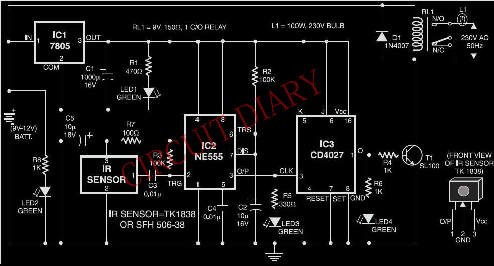
 The circuit is built around a 3-pin IR IC receiver (Siemens SFH-506-38 or equivalent) that can detect 38kHz burst frequency  generated by a TV remote.
 The output pin of IR sensor goes low when it detects IR light, triggering the monostable (1-second) built around timer NE555. The output of the mono toggles the J-K flip flop, whose Q output drives the relay through SL100 npn transistor (T1).
 LED2, LED3, and LED4 are used to display the status of each output stage during circuit operation. Back-EMF diode D5 is used for protection. Transistor T1 is configured as an open-collector output device to drive the relay rated at 12V DC.
 The circuit draws the power from voltage regulator 7805. Capacitor C5 is soldered close to the IR sensor’s pins to avoid noise and false triggering. Capacitor C3 and resistor R3 also avoid false triggering of  monostable NE555. The monostable acts as a 1-second hysterisis unit to restrict the flipflop from getting retriggered within one second. To activate any other 12V logic device, use the output across the relay coil terminals.

Wednesday, June 15, 2011

INTELLIGENT SWITCH


 This intelligent switch circuit en- ables automatic switching on of an emergency light system during darkness in the event of mains failure. The mains power failure condition is detected by the section consisting of mains step-down transformer X1 followed by bridge rectifier comprising diodes D1 through D4 and smoothing capacitor C1. If the mains is available then it causes energisation of relay RL1 which has two sets of changeover contacts. 
fig:1:circuit of Intelligent Switch,Click  on image to enlarge


  The light/darkness condition is detected by the circuit comprising photo-transistor FPT100/2N5777 followed by Darlington pair comprising transistors T2 and T3. However, this section will function only when mains supply is not available (i.e. when relay RL1 is in de-energised state) since battery supply (negative lead) path gets completed via lower N/C contact of relay RL1. During daylight, photo transistor conducts and places transistor T2 base near ground potential. Thus Darlington pair remains cut-off and relay RL2 remains de-ene- rgised. However, during darkness, ph- oto transistor is cut-off and therefore transistor T2 receives forward base bias via resistor R1 (connected to positive rail), as resistor R2 is no more grounded (via photo-transistor T1).
   As a result, relay RL2 gets energised. Thus it would be observed that when mains is absent (relay RL1 deenergised)  and it is dark (relay RL2 energised), the switch output path is complete. In any other condition switch output path would get broken. 
 The switch output terminals can be used (in series with supply) to control a lighting system directly or indirectly through another contactor/heavy-duty relay depending upon the load. The working of the intelligent switch is summarised in the table.

Tuesday, June 14, 2011

Staircase Light with Auto Switch-off


We are all familiar with the electrical wiring arrangement that connects an electrical bulb with two switches: one at the bottom of a staircase and the other at the top. Wiring is done such that either of the two switches can be used to switch the bulb on or off. In such a wiring arrangement, while climbing up the staircase which is in dark, the switch located at the bottom of the staircase is used to switch on the light. After you have climbed the staircase, you use the switch located there to switch off the light.

  The circuit presented here is an electronic-cum-electrical arrangement to get a similar facility as provided by the hard-wired electrical system, but you need to operate the switch only once. Whereas in the hard-wired arrangement if you forget to switch off the light once you have  traversed the staircase, light would remain ‘on, wasting energy.
  In this circuit also, we have two micro-switches—one located at the top and the other located at the bottom of the staircase—that can be pushed and released easily during climb-up from the bottom of the staircase or climbdown from the top of the staircase. With every push and release of either of the two switches, bulb L1 lights up for a preset time period of, say, 40 seconds, which is considered adequate for climbing up or going down the staircase. The bulb goes off automatically after the set 40 seconds. You can change this ‘on’ time by changing the values of resistor R7 and/or capacitor C4 depending upon your requirement.
  Switches S1 and S2 are the two micro-switches, which provide low inputs to the respective de-bouncing circuits. Each de-bouncing circuit is built around two NAND gates connected back to back. The de-bouncing circuits ensure a clean, bounce-free pulse at the output every time the micro-switch is pressed and released. The outputs from the two de-bouncing circuits are  ORed using diodes D1 and D2 (1N4001). So every time you press and release either of the micro-switches, you get a positive going pulse at the junction of the cathodes of diodes D1 and D2.
  These pulses are used to trigger the monostable circuit built around timer IC2. On the trailing edge of the pulse, the output of the monostable goes high for a time period of 40 seconds. This drives relay-driver transistor 2N2222 (T1) wired as a switch. Relay RL1 gets energised and closes N/O contacts of the relay, wired in series with the mains and the bulb (L1). Bulb L1 switches off when the relay gets de-energised after 40-second pulse period. Free-wheeling diode D4 (1N4001) protects transistor T1 against transients during relay switch-off operation.
  The circuit operates off a 9V battery, which gets connected to the circuit through ‘on’/‘off’ switch S3. You can also use regulated 9V power supply. Assemble the circuit on a  general purpose PCB and house in a small box. Connect micro-switches S1 and S2 near top and bottom of the staircase through flexible wires and bulb in the middle of the staircase.

DARK SENSITIVE SWITCH


  This circuit will activate a relay when light falls to a preset level. Light level can be adjusted with VR1 and the relay contacts may be used to operate an external light or buzzer.
   The light sensor used is the ORP12 photocell. In bright light the resistance of the ORP12 can be as low as 80 ohm and at 50lux (darkness) the resistance increases to over 1 Mohm. The 1M control should provide a wide range for light intensities, if not its value may be increased. The op-amp senses the voltage difference between pins 2 and 3. The control VR1 is adjusted so that the relay is off, the output of the op-amp will be around 2 Volts. When light falls, the resistance of the photocell increases and the difference in input voltage is amplified by the op-amp, the output will swing towards full supply and drive the transistor and relay. 

  The 270k resistor provides a small amount of hysteresis, so that the circuit switches on and off with slightly different light levels. This eliminates relay chatter. Take great care if you decide to wire the relay to activate a mains lamp. Make sure the relay contacts provide adequate isolation and have ample rating for the load.      The thermistor used has a resistance of 15k at 25 degrees and 45k at 0 degrees Celsius. A suitable bead type thermistor is used. The 100k pot allows this circuit to trigger over a wide range of temperatures. A slight amount of hysteresis is provided by inclusion of the 270k resistor. This prevents relay chatter when temperature is near the switching threshold of this circuit.

Monday, June 13, 2011

ALTERNATING ON-OFF SWITCH

   Use this circuit instead of a standard on-off switch. Switching is very gentle. Connect unused input pins to an appropriate logic level (I used ground). Unused output pins  MUST be left open!
First 'push' activates the relay, another 'push' de-activates the relay.

  IC1, the MC14069 (or 4069) is a regular Hex-inverter type and is constructed with MOS P-channel and N-channel enhancement mode devices in a single monolithic structure. It will operate on voltages from 3 to 18 volts, but most applications are in the 5 to 15 volts. Although the 4069 contains protection circuitry agains damage from ESD (Electro Static Discharge), use common sense when handling this device. Depending on your application you may want to use an IC-socket with IC1. It makes replacement easy if the IC ever fails.
  You can use any type of 1/4 watt resistors including the metal-film type.
  The type for D1 in not critical, even a 1N4148 will work. But, depending on your application I would suggest a 1N4001 (or similar) as a minimum.
  Any proper replacement for Q1 will work, including the european TUN's. Since Q1 is just a driver to switch the relay coil, almost any type for the transistor will do. PN100, NTE123A, 2N3904, 2N2222, 2N4013, etc. will all work. For C2, if you find the relay acts not fast enough, you can change it to a lower value or use a ceramic cap of around 0.1μF. It is there as a spark-arrestor together with the diode (D1). For the relay I used a 6 volt type with the above circuit and 9 volt battery. The circuit will work fine with 12 Volt, the only
thing to watch for is the working voltage of C2; increase that to 25V if you use a 12V supply.
  I added the Led to have a visual indication of being 'on'. For use with 12V supply make R4 390 ohms. The LED and R4 are of course optional and can be left out. Your application may already have some sort of indicator and so the LED and R4 are not needed.

Twitter Delicious Facebook Digg Stumbleupon Favorites More