Monday, June 27, 2011

Audio Perimeter Monitor


This circuit is intended for audio surveillance of an unattended area, examples being a back garden or open space. It can be used to listen for wildlife or just as an extra pair of ears. 
Click to enlarge

Using a single cable such as speaker wire or doorbell cable, this circuit can be remotely positioned, for example, at the bottom of a garden or garage, and used to detect all sound in that area.  The cable can be buried in a hosepipe or duct and is concealed out of sight. The mic is an ordinary dynamic mic insert and should be housed in a waterproof enclosure with the rest of the circuit. The mic output is amplified by the two transistors, the output is fed down the cable via the 220u capacitor. Here, it has a dual purpose of preventing the DC supply from upsetting the bias of the circuit, and also allowing the smaller ac audio output to pass down the line. At the power supply, the audio is recovered by the 10k preset and 220u capacitor. It is used to feed a small audio amplifier (such as the 2watt design) shown earlier on this site. 

security Alarm circuit


As you can clearly see from the schematics, the circuit is utterly primitive and consists of two identical transistor switches. Each has its own alarm LED and they're coupled to a neat 82dB buzzer.
click to enlarge

The two 1N4148 diodes are used to prevent a signal from one sensor from triggering both LEDs. The sensors used are either wire loops or normally closed reed switches or even a combination of both. You could, for example, tie a wire loop to your suitcase and place a reed switch to the door of your hotel room.
Since this little alarm is intended to be kept in arms reach at all times, there aren't any provisions for automatic shutdown after a certain period of time. The buzzer will sound until you turn the whole circuit off or connect the wire loop back to the jumpers. The same goes for the two LEDs, each indicating its own zone.
Construction is not critical and there aren't any traps for the novice. The two 100n capacitors aren't really necessary, I just included them to make sure that there is no noise interference coming from the long wire loops. For transistors, you can use any NPN general-purpose audio amplifiers/switches (BC 107/108/109, BC 237/238, 2N2222, 2N3904...). Assemble the circuit on perf board. Together with the buzzer and a 9V battery, it should easily fit in a pocket-sized plastic box smaller than a pack of cigarettes. A fresh battery should suffice for weeks of continuous operation.

Phone Amplifier


While talking to a distant sub- scriber on telephone, quite often we feel frustrated when the voice of the distant subscriber is so faint that it is barely intelligible. 
click to enlarge

To overcome the problem, circuit of an inexpensive amplifier is presented here. It can be assembled and tested easily. There is no extra power source needed to power up the circuit, as it draws power from the telephone line itself. The amplifier will provide fairly good volume for the telephone conversation to be properly heard in a living room. A volume control is included to adjust the volume as desired. The circuit is built around IC LM386. Diodes D6 and D7 are used to limit the input signal strength. Transformer X1 is a transistor radio’s output transformer used in reverse. As original secondary (output) winding is connected in series with the telephone lines, the speech signals passing through the lines cause change in the magnetic flux in the core of transformer and thereby induce signal voltage across the primary winding. This audio signal is used as input for IC LM386. Diodes D2 through D5 connected in bridge configuration constitute a polarity guard so that the amplifier is powered with correct polarity, irrespective of the line polarity, Zener diode D1 may have any breakdown voltage between 6 and 12 volts range. There is no need of a separate power switch as the circuit energises (via the normally open contacts of the cradle switch) when one lifts the handset. The circuit may be wired on a general-purpose PCB or by etching a PCB for this circuit. The circuit can be easily tested by connecting a 6 volts supply to line terminals 1 and 2. A hissing sound will be heard from the loudspeaker. Now connect 6V AC from a transformer to terminals 1 and 2 and observe hum in the loudspeaker. The volume of the hum can be changed through potentiometer VR1. Diodes D6 and D7 limit the input below ± 700 mV. The circuit is to be connected to the telephone lines in series with the telephone instrument, as shown in the figure.

Object Counter Circuit


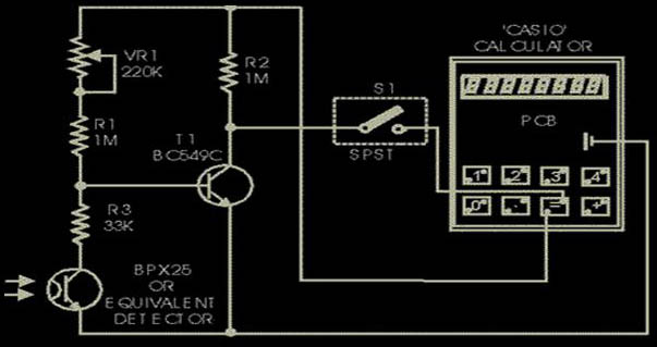
Presented here is the cheapest 8-digit programmable object or event counter. It is a fail-proof, fool-proof, power failure-proof, one evening project. A general-purpose (arithmetic) calculator has some inherent shortcomings which can, however, be used in many ways by proper programming sequences.
click to enlarge

For example, there is no squaring key in a general-purpose calculator, but it can not only square it has even the inherent capability of a single touch successive multiplication, thus giving us a choice of making a geometric progression (G.P.) or successive addition or forming an arithmetic progression (A.P.). For example, operating the keys 5,x,=,=,... you obtain the G.P. 5,25,125,625,... or by operating keys 5,x,4,=,=,=,..., you get the G.P.: 4,20, 100,500,... Next, operate keys: 5,+, 2,=,=,... to get the A.P.: 5,7,9,11,13,... The latter facility (A.P.) has been used here to count the objects by programming the calculator keys 1,+,=,=,... When you open the calculator (such as ‘Casio’), you will find that the conductive silicon key pads bridge the two terminals of a key, when depressed. Locate the switch terminals for (=) key and check the polarity of the terminals with respect to the battery negative. The terminal which is found to be positive is to be connected to the junction of R2 and VR1, and the other terminal is to be connected to switch S1 as shown in the figure. The negative battery terminal is to be connected to emitters of photo-transistor and transistor T1. (There may be slight difference in the use of key terminals in different brands of calculators.) The optical sensor used here is BPX25, a very sensitive photo-transistor which has a built-in lens to focus the incident light on to the chip. Only two leads, emitter and collector, have been used. When light falls on the sensor, it conducts as if it had got forward biased. A variable resistor of 220k in series with another fixed resistor of 1 M (selected by trial) has been used at the base of transistor T1 (BC149C/BC 549C) to set the threshold level for its conduction, depending upon the intensity of light used. When light is obstructed, BPX goes to cut-off, transistor T1 conducts and the terminal of (=) key which is connected via switch S1 (assuming closed), goes low. This is equivalent to depression of the (=) key. When light again falls on the sensor, it conducts and the base of transistor T1 goes low, throwing it to cut-off, so that its collector and hence the (=) key gets connected to the positive bus via 1 M resistor R2. A pulse is passed on and the calculator advances by 1. Current drain from the battery is less than 50 µA, which a button cell can easily provide. The counter is slow but there is no switch debouncing effect present, which makes the counter highly reliable and ideal as a slow event counter in applications such as visitor counter. Further, the circuit is auto-locked, since any resetting is possible only when BPX is in the cut-off position, i.e., in darkness. To program, cover the phototran- sistor and operate keys : 1,+,=. In case of a deadlock in programming, miniature switch S1 may be used to enable isolation of the (=) key. Set the 220k preset according to the ambient and the incident light, so that the calculator counts when light is cut-off and again allowed to fall when obstruction is removed. If it is used to count visitors in a well day-lighted environment, only a white washed wall or a white paper pasted on the opposite door panel is sufficient. For indoor applications, a specific source of light is required. Both the source of light as well as the BPX should then be mounted in opaque (preferably black) tubes and a lens be fitted in the light-source tube to focus the light on to the photo-transistor. BC149C/549C is preferred due to its large current gain of the order of 300 at 10 µA, compared to 150 that of BC548B, so that the instrument becomes more sensitive.

Water Tank Overflow Preventer


There is practically no house without an overhead tank (OHT). People who use electrically-operated water pumps for filling the OHT find it very inconvenient to switch off the pump when their overhead tank starts overflowing, specially when they are busy. So there is plenty of water wastage as well as wastage of power (consumed by the pump). However, there is a solution to get rid of this headache. 
click to enlarge

The circuit given here will switch off the pump and also generate a melodious tune when the overhead tank gets filled up to the maximum desired level. All you have to do is switch off the power supply to the circuit when you are relatively free. The heart of the circuit is the CMOS latch CD4001. Usually the latch can be operated in two modes, namely, set and reset mode, i.e. the latch output can be set to logic 1 or reset to logic 0 by applying appropriate active low level input signal to pins 1 and 13, respectively. Here, in the given circuit, the set point is pin 1 and the reset point is pin 13. The inverted output of the latches are obtained at pins 3 and 11, respectively. When the circuit is powered there is a voltage drop at pin 1 due to the resistor-capacitor R1-C1 combination. The values of resistor R1 and C1 are chosen in such a way that pin 1 is low for about two seconds which is sufficient to energise the relay through transistor T1 and thus the pump starts running. When sufficient water gets filled in the overhead tank, switch S1 in the sensing unit, in the overhead tank as shown in Fig. 2, sends an active low signal to pin 13 which resets latch gate N1 output to logic 0. This causes transistor T1 to stop conducting, thereby de-energising the relay and shutting down the pump. At the same time, the output at pin 11 of gate N2 will be logic 1. This results in conduction of transistor T2 and melodious buzzer sounds. The green LED also lights up while the red LED, which remains on as long as the relay remains energised, gets switched off when water reaches the specified level in the overhead tank. The circuit possesses the following advantages:
1.    Special sensing mechanism (easy to build) is used to sense the water level in the overhead tank.
2.    One can replace CD4011 with IC 7400. In that case, a 5.1V zener may be connected additionally between pin 14 of IC1 and the ground.
The circuit can be easily fabricated on a general-purpose PCB.

Audio amplifier output relay delay


Component list
C1    100 uF 40V electrolytic
C2    100 uF 40V electrolytic
D1    1N4007
D2    1N4148
Q1    BC547
R1    33 kohm  0.25W
R2    2.2 kohm 0.25W
RELAY 24V DC relay, coil resistance >300 ohm
click to enlarge

Circuit operation
Then power is applied to the power input of the circuit, the positive phase of AC voltage charges C1. Then C2 starts to charge slowly through R1. When the voltage in C2 rises, the emitter output voltage of Q1 rises tigether with voltage on C2. When the output voltage of Q2 is high enough (typically around 16..20V) the relay goes to on state and the relay witches connect the speakers to the amplifier output. It takes typically around 5 seconds after power up until the relay starts to condict (at absolute time depends on the size of C2, relay voltage and circuit input voltage).
When the power is switched off, C1 will loose it's energu quite quicly. Also C2 will be charged quite quicly through R2. In less than 0.5 seconds the speakers are disconnected from the amplifier output.
Notes on the circuit
This circuit is not the most accurate and elegant design, but it has worked nicely in my small homebuilt PA amplifier. This circuit can be also used in many other applications where a turn on delay of few seconds is needed. The delay time can be increased by using bigger C2 and decreased by using a smaller C2 value. Note that the delay is not very accurate because of simplicity of this circuit and large tolerance of typical electrolytic capacitors (can be -20%..+50% in some capcitors).

Motor Speed controler

 
The circuits shown below are a few of many suggested circuits as published by SCR and TRIAC manufacturers and cannot be construed as beeing the exact application for your requirements and I cannot be held responsible for their use and end results . 

click to enlarge

It is suggested that the subject of TRIAC and SCR as well as motor drive control systems be researched before making a final decision as to the application of these control circuits .
For satisfactory and safe results, knowing the exact type of motor you wish to control is of prime importance and all data available should be obtained before you contemplate to add any drive control circuits . Mount all SCR's and Triac on heatsink . Use current rated stranded wiring as required .
If you cannot find the SCR's and TRIAC's suggested in the circuits you may be able to find a substitute following this link Cross References
Some links to SCR's,TRiac's and motor control application notes:

Thyristors
Application Notes
Triac Data
NTE Triac Selection
NTE SCR Selection
You can use a transformer with up to 12 amps output current with corresponding fuse value . Use No.12-14 stranded wiring to battery connection with heavy duty clips .
Mount Rectifiers and SCR's on heatsink . You can use a mA meter with a shunt resistor . See
Metering a power supply .
Note The rectifiers and SCR's value as quoted can be changed to lesser values as required for lower current output .


Night Rider Light For Bikes


Always looking for ways to be seen at night. So wanted something that was a novelty and would catch the motorists eye. So looking around at  fellow cyclists rear lights, Its is a Hobby circuit for bikes,'NITE-RIDER'. NINE extra bright LED's running from left to right and right to left continuously. It could be constructed with red LEDs for use on the rear of the bike or white LED's for an extra eye catcher on the front of the bike.

click to enlarge


All IC's are CMOS devices so that a 9V PP3 battery can be used, and the current drawn is very low so that it will last as long as possible.


The circuit comprises of ...


1 555 timer IC4.
1 4027 flip flop IC1.
2 4017 Decade Counter IC2 and IC3.
3 4071 OR gate IC5, IC6 and IC7.
1 470 Ohm resistor 1/4 watt R3.
2 10K resistors 1/4 watt R1 and R2.
1 6.8UF Capasitor 16V C1.
9 Super brght LED's 1 to 9.
1 9V PP3 Battery.
1 single pole switch SW1.
1 Box.


How The Circuit Works.


IC4, C1, R1 and R2 are used for the clock pulse which is fed to both the counters IC2 and IC3 Pin 14.


IC1 is a Flip Flop and is used as a switch to enable ether IC2 or IC3 at pin 13.


IC7a detects when ether IC2 or IC3 has reached Q9 of the counter pin 11.


IC5, IC6 and IC7a protects the outputs of the counters IC2 and IC3 using OR gates which is then fed to the Anodes of the
LED's 1 to 9

LEDs Display


The circuit presented here uses bicolour LEDs to generate a display in three colours, namely, red,green, and yellowish green. Transistors T1 through T20 form a grid to which common-cathode bicolour LEDs (LED1 through LED10) are connected. 
click to enlarge

 Transistors T1 through T10 have their collector terminals connected to the emitter of transistor T21. Similarly, transistors T11 through T20 have their collector terminals connected to the emitter of transistor T22. The bases of each pair of transistors (i.e.  T1 and T11, T2 and T12,…, T10 and T20) are tied to outputs Q0, Q1,…, Q9, respectively, of IC1 (CD4017) through 10-kiloohm resistors as shown in the figure. Positive supply to collectors of transistors T1 through T10 is controlled by transistor T21. Similarly, positive supply to collectors of  transistors T11 through T20 is controlled by transistor T22.
IC1 and IC2 are decade counters. Clock pulse to IC1 is provided by the oscillator circuit comprising NOR gates N1 and N2. The outputs of IC1 advance sequentially  with each clock. (Any other source of squarewave pulses also serves the purpose.)IC2 is used to select the mode of display. Clock input pin 14 of IC2 is connected to Q9 output of IC1. Thus IC2 receives one pulse after every ten pulses received by IC1.
  When the circuit is switched on, Q0 output of IC2 is active high. Thus transistor T21 gets forward biased via diode D3 and it conducts to extend positive supply to transistors T1 through T10. Transistors T1 through T10 are forward biased sequentially by Q0 through Q9 outputs of IC1, i.e. at a time only one of these ten transistors is forward biased (on). Thus only red LED parts of bicolour LEDs light up sequentially.  Transistor T22 is not conducting at this moment.) When red LED part of LED10 glows, IC2 receives a clock pulse and its Q1 output goes high. Transistor T21 still conducts, as it is forward biased through diode D6, and next again via diode D5. Thus red LEDs complete two more glowing sequences.
 After completion of the third glowing sequence of red LEDs, when Q3 output of IC2 goes high, transistor T21 stops conducting and T22 starts conducting with the next three sequences of green LEDs of bicolour LEDs (LED1 through LED10) glowing sequentially. After completion of three sequences of green LEDs, output Q6 of IC2 goes high.
Now both transistors T21 and T22 conduct due to diodes D1 and D2. Thus both red and green LEDs in bicolour LEDs (LED1 through LED10) glow sequentially. The effect of red and green LEDs glowing together is a distinct yellowish orange colour. This sequence repeats four times.
Thereafter, the whole sequence repeats, starting with red LEDs. Thus the bicolour LED display shows three colours—red, green, and yellowish green—one after the other. The speed of display can be controlled by preset VR1. One can omit automatic selection of different colours by omitting IC2 and replacing connections to pins 3, 5, and 7 of IC2 with SPDT switches. (Thus diodes D3-D12 are also omitted.)

IR Headphone


Using this low-cost project one can reproduce audio from TV without disturbing others. It does not use any wire connection between TV and headphones. In place of a pair of wires, it uses invisible infrared light to transmit audio signals from TV to headphones. Without using any lens, a range of up to 6 metres is possible. Range can be extended by using lenses and reflectors with IR sensors comprising transmitters and receivers.
click to enlarge

 IR transmitter uses two-stage transistor amplifier to drive two series-connected IR LEDs. An audio output transformer is used (in reverse) to couple audio output from TV to the IR  transmitter. Transistors T1 and T2 amplify the audio signals received from TV through the audio transformer. Lowimpedance output windings (lower gauge or thicker wires) are used for connection to TV side while high-impedance windings are connected to IR transmitter.  
This IR transmitter can be powered from a 9-volt mains adapter or battery. Red LED1 in transmitter circuit functions as a zener diode (0.65V) as well as supply-on indicator. IR receiver uses 3-stage transistor amplifier. The first two transistors (T4 and T5) form audio signal amplifier while the third transistor T6 is used to drive a headphone. Adjust potmeter VR2 for max. clarity.

Direct photo-transistor towards IR LEDs of transmitter for max. range. A 9-volt battery can be used with receiver for portable operation.

Mains Manager


Very often we forget to switch off the peripherals like monitor, scanner, and printer while  witching off our PC. The problem is that there are separate power switches to turn the peripherals off. Normally, the peripherals are connected to a single of those four-way trailing sockets that are plugged into a single wall socket. If that socket is accessible, all the devices could be switched off from there and none of the equipment used will require any modification.
click to enlarge

 Here is a mains manager circuit that allows you to turn all the equipment on or off by just operating the switch on any one of the devices; for example, when you switch off your PC, the monitor as well as other equipment will get powered down automatically.  You may choose the main equipment to control other gadgets. 
The main equipment is to be directly plugged into the master socket, while all other equipment are to be connected via the slave socket. The mains supply from the wall socket is to be connected to the input of the mains manager circuit. The unit operates by sensing the current drawn by the control equipment/load from the master socket. On sensing that the control equipment is on, it powers up the other (slave) sockets. The load on the master socket can be anywhere between 20 VA and 500 VA, while the load on the slave sockets can be 60 VA to 1200 VA.
 During the positive half cycle of the mains AC supply, diodes D4, D5, and D6 have a voltage drop of about 1.8 volts when current is drawn from the master socket. Diode D7 carries the current during negative half cycles. Capacitor C3, in series with diode D3, is connected across the diode combination of D4 through D6, in addition to diode D7 as well as resistor R10. Thus current pulses during positive half-cycles, charge up the capacitor to 1.8 volts via diode D3. This voltage is sufficient to hold transistor T2 in forward biased condition for about 200 ms even after the controlling load on the master socket is switched off.
 When transistor T2 is ‘on’, transistor T1 gets forward biased and is switched on. This, in turn, triggers Triac 1, which then powers the slave loads. Capacitor C4 and resistor R9 form a snubber network to ensure that the triac turns off cleanly with an inductive load.
 LED1 indicates that the unit is operating. Capacitor C1 and zener ZD1 are effectively in series across the mains. The resulting 15V pulses across ZD1 are rectified by diode D2 and smoothened by capacitor C2 to provide the necessary DC supply for the circuit around transistors T1 and T2. Resistor R3 is used to limit the switching-on surge current, while resistor R1 serves as a bleeder for rapidly discharging capacitor C1 when the unit is unplugged. LED1 glows whenever the unit is plugged into the mains. Diode D1, in anti-parallel to LED1, carries the current during the opposite half cycles.
 Don’t plug anything into the master or slave sockets without testing the unit. If possible, plug the unit into the mains via an earth leakage circuit breaker. The mains LED1 should glow and the slave LED2 should remain off. Now connect a table lamp to the master socket and switch it ‘on’. The lamp should operate as usual. The slave LED should turn ‘on’ whenever the lamp plugged into slave socket is switched on. Both lamps should be at full brightness without any flicker. If so, the unit is working correctly and can be put into use.
 Note. 1. The device connected to the master socket must have its power switch on the primary side of the internal transformer. Some electronic equipment have the power switch on the secondary side and hence these devices continue to draw a small current from the mains even when switched off. Thus such devices, if connected as the master, will not control the
slave units correctly.
2. Though this unit removes the power from the equipment being controlled, it doesn’t provide isolation from the mains. So, before working inside any equipment connected to this unit, it must be unplugged from the socket.

Heat Detector


This circuit uses a complementary pair comprising npn metallic transistor T1 (BC109) and pnp germanium transistor T2 (AC188) to detect heat (due to outbreak of fire, etc) in the vicinity and energise a siren. The collector of transistor T1 is connected to the base of transistor T2, while the collector of transistor T2 is connected to relay RL1. 
click to enlarge

 The second part of the circuit comprises popular IC UM3561 (a siren and machine-gun sound generator IC), which can produce the sound of a fire-brigade siren. Pin numbers 5 and 6 of the IC are connected to the +3V supply when the relay is in energised state, whereas pin 2 is grounded. A resistor (R2) connected across pins 7 and 8 is used to fix the frequency of the inbuilt oscillator. The output is available from pin 3.
  Two transistors BC147 (T3) and BEL187 (T4) are connected in Darlington configuration to amplify the sound from UM3561. Resistor R4 in series with a 3V zener is used to provide the 3V supply to UM3561 when the relay is in energised state. LED1, connected  in series with 68-ohm resistor R1 across resistor R4, glows when the siren is on.
 To test the working of the circuit, bring a burning matchstick close to transistor T1 (BC109), which causes the resistance of its emitter-collector junction to go low due to a rise in temperature and it starts conducting. Simultaneously, transistor T2 also conducts because its base is connected to the collector of transistor T1. As a result, relay RL1 energises and switches on the siren circuit to produce loud sound of a firebrigade siren.
Lab note. We have added a table to enable readers to obtain all possiblesound effects by returning pins 1 and 2 as suggested in the table.

Twitter Delicious Facebook Digg Stumbleupon Favorites More